 2015, Vol. 36
Shanghai University
Article Information
- Yanzheng WANG, Weiqiu CHEN, Xiangyu LI. 2015.
- Statics of FGM circular plate with magneto-electro-elastic coupling: axisymmetric solutions and their relations with those for corresponding rectangular beam
- Appl. Math. Mech. -Engl. Ed., 36(5): 581-598
- http://dx.doi.org/10.1007/s10483-015-1934-7
Article History
- Received 2014-06-20;
- in final form 2014-10-07


2. State Key Laboratory of CAD & CG, Zhejiang University, Hangzhou 310058, China;
3. School of Mechanics and Engineering, Southwest Jiaotong University, Chengdu 610031, China
Smart materials, such as piezoelectric and piezomagnetic materials, have been widely applied in numerous engineering fields in recent years. As a special kind of smart materials, magneto-electro-elastic (MEE) or multiferroic materials possess more physical fields than the single phase piezoelectric or piezomagnetic materials, and exhibit a magnetoelectric effect macroscopically. Owing to the multi-field coupling property, the energy in MEE composites can be converted from one form to another, providing new functions for device applications[1, 2].
Heretofore, intensive academic efforts have been made on mechanical behaviors of MEE materials. For example, Pan[3], using a propagator matrix method, derived an exact closedform solution for a simply supported and multilayered MEE plate under a static mechanical load. Zhou and Wang[4] investigated the behavior of an interface crack in MEE composites by use of the Schmide method. For an MEE solid containing an elliptical inclusion, Jiang and Liu[5] obtained the exact general solution. Using the state-vector approach, Chen et al.[6] investigated the propagation of harmonic waves in MEE multilayered plates.
To prepare thermal barrier materials, Japanese scientists firstly proposed the concept of functionally graded materials (FGMs) whose material properties vary continuously with spatial coordinates[7]. Studies on the performance of functionally graded magneto-electro-elastic (FGMEE) materials are very popular at present. For instance, Chen et al.[8, 9] analyzed the bending and free vibration of FGMEE plates using a new state-space formalism. For a multilayered FGMEE plate, Pan and Han[10] derived exact static bending solutions by taking advantage of the pseudo-Stroh formula as well as the propagator matrix method. Bhangale and Ganesan[11] carried out a numerical analysis of bending of a layered heterogeneous anisotropic MEE plate by means of a semi-analytical finite element method. Huang et al.[12] studied the plane stress problems of an FGMEE beam and developed an elegant approach to derive the closed-form elasticity solutions based on the stress function formalism.
This paper aims to study the multi-field response of an FGMEE circular plate subjected to certain mechanical loads. The problem of circular plates under external loads is a classic issue in the theory of elasticity[13]. For FGM circular plates under non-uniform axisymmetric loadings, Wang et al.[14, 15, 16] developed a generalized Fourier series expansion technique to obtain 3D exact solutions. Yang et al.[17, 18] extended the study of Mian and Spencer[19] to FGM circular plates. For the axisymmetric problems of FGM circular plates, Li et al.[20, 21, 22, 23, 24] obtained a series of analytical elasticity solutions via the direct displacement method or the stress function method. In particular, Li et al.[24] presented 3D analytical solutions for a piezoelectric FGM circular plate under tension and bending.
In this paper, we extend the study in Ref. [24] to an FGMEE circular plate subjected to tension and bending via the direct displacement method. In this method, the generalized displacements (including elastic displacements, magnetic potential, and electric potential) are expressed as polynomials of the radial coordinate variable, with the coefficients however being (continuous) functions of the thickness coordinate variable. These coefficient functions will be referred to as displacement functions later in this paper. The equations governing the displacement functions are readily derivable from the equilibrium equations. The analytical expressions for the displacement functions are then derived through a step-by-step integration scheme with the aid of the boundary conditions on the upper and lower surfaces of the plate. The five integral constants are finally determined from the cylindrical boundary conditions in the Saint Venant sense.
Another contribution of this paper is that we find that intrinsic relations exist between the analytical solutions derived here for an FGMEE circular plate and those for an FGMEE straight rectangular beam. The latter can be found from Ref. [12], which were obtained by the stress function method, and are re-derived here also using the direct displacement method. The similarity between the plate solutions and the beam solutions is not obvious, though the side views of these two structures are identical. We further notice that these correspondence relations may be established among a broader range of material pairs, which will be shown mathematically in the paper.
The outline of the paper is as follows. Section 2 presents the analytical solutions of an FGMEE circular plate, while those for an FGMEE rectangular beam are given in Section 3, both by the direct displacement method. The correspondence between the circular plate solutions and the beam solutions is shown in Section 4, which is valid when all the material constants vary in the same way along the thickness direction. Some numerical examples are presented in Section 5, while a summary of the present study is given in Section 6. 2 Analytical solutions for FGMEE circular plate 2.1 Basic equations and problem description
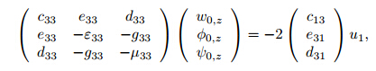
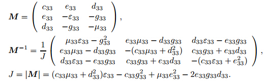
In the cylindrical coordinate system (r, θ, z) with the z-axis coincident with the polarization direction, the equilibrium equations and the constitutive relations for axisymmetric problems of a transversely isotropic FGMEE body are[20]
where the subscript comma denotes differentiation with respect to the indicated variable; σr, σθ, σz, and τrz are the stress components; Dr and Dz are the electric displacement components; Br and Bz are the magnetic induction components; u and w are the displacements in the radial and thickness directions; and cij, eij, εij, gij, μij, and dij are the elastic, piezoelectric, dielectric, magnetoelectric, magnetic and piezomagnetic coefficients, respectively.
In the present paper, we consider an FGMEE circular plate with radius a and height h, as shown in Fig. 1. The origin of the coordinates is set at the center of the plate. All material constants appearing in (2) are assumed to be functions of the thickness coordinate (i.e., z). Both the upper and lower surfaces are free from tractions, electric displacement and magnetic induction, i.e.,
At r = a, the plate is subjected to a prescribed radial force N and a bending moment M, i.e.,

 |
| Fig. 1 Geometry of circular plate and applied load |
To solve the aforementioned boundary value problems, we adopt the direct displacement method[20, 23, 24], and assume that
where u1(z), w1(z) (n = 0, 2), φ0(z), and ψ0(z) are referred to as the (generalized) displacement functions.
Substituting (4) into (2), we can get the (generalized) stresses (stress, electric displacement, and magnetic induction) expressed by the displacement functions. Introducing these expressions into (1) and letting the coefficients of each power of r vanish, we then get
These are the differential equations governing the displacement functions, which are functions of z only.
In view of (4) and (2), the boundary conditions (3a) can be written as

We notice that there are certain relations between the terms in (5) and (6). For example, the second term in (5b) is just the derivative of the left-hand side of (6a). Such relations are the key in the direct displacement method, which allows a step-by-step integration procedure to determine the displacement functions, as shown below.
Integrating (5c), (5e), and (5g) once from the lower limit z = −h/2 and using the boundary conditions (6b), (6e), and (6g), we arrive at
Clearly, (7) is equivalent to Substitution of (8) into (5a) and utilization of the boundary condition (6c) give rise to or


Introducing (10) into (5b), (5d), and (5f), we can obtain the following equations with the help of (6a), (6d), and (6f):

Now we have five first-order differential equations in (8), (10), and (11) to determine the five displacement functions. Integrating (8) and (10), we can readily arrive at
where a1 and a2 are integral constants, which can be determined from the cylindrical boundary conditions (3b). Meanwhile, (11) can be written as


Integrating both sides of (14), we can derive the expressions of w0, φ0, and ψ0 as
with
 , and
a5 are integral constants, corresponding to a rigid-body translation in the axial direction, a
reference electric potential and a reference magnetic potential, respectively. They have no
influence on the distributions of the generalized stresses in the plate. Therefore, only two
integral constants a1 and a2 need to be determined in the following.
2.3 Explicit analytical solutions
, and
a5 are integral constants, corresponding to a rigid-body translation in the axial direction, a
reference electric potential and a reference magnetic potential, respectively. They have no
influence on the distributions of the generalized stresses in the plate. Therefore, only two
integral constants a1 and a2 need to be determined in the following.
2.3 Explicit analytical solutionsSubstituting (12) and (15) back into (4), we obtain
From (16) and (2), we have where Substituting (17b) into (3b), we obtain with


Solving (19) simultaneously, we can determine the integral constants a1 and a2 as
with D = 2N2N0 − 2NN12.
Inserting (20) into (16) and (17), we can get the explicit expressions of non-zero displacements and stresses as follows:

For a simply-supported circular plate, we assume that the axial displacement w vanishes at the plate edge on the middle plane (i.e., r=a, z=0). This gives
For a homogeneous MEE circular plate, the material properties are all constant, and (21) and (22) are reduced to
Since all material properties are independent of z, F in the above equations is also a constant which can be computed through (18).
Various decoupled cases such as the electroelastic, magnetoelastic, and elastic plates could be dealt with by a proper degeneration analysis. In fact, the corresponding solutions could be obtained by letting eij, dij or gij vanish. It could be readily found that the degenerate solutions for the piezoelectric plates are identical with those reported in Ref. [24], while the solutions for the elastic plates are the same as those in Ref. [13]. 3 Corresponding solutions for FGMEE rectangular beam
It is interesting to note that a rectangular beam has the same side view as a circular plate (see Figs. 2(a) and 2(b)). However, these two typical structures are actually quite different in many aspects, and hence no one has thought about the possibility of establishing the correspondence between the solutions for a circular plate and those for a rectangular beam. In the next section, we show that this is possible even for FGMs when all material properties vary in the same way along the thickness direction. This section first present the solutions for an FGMEE rectangular beam, which has already been investigated by Huang et al.[12] using the stress function method. Here, we revisit the problem by the direct displacement method. For plane problems of rectangular beams, the equilibrium equations and the constitutive relations in Cartesian coordinates are
Here, u and w are the displacements in the longitudinal and transverse directions of the beam. Note that the material constants cij, eij, dij, εij, gij, and μij in (26) for beam problems are generally different from those in (2) for plate problems. The former are usually referred to as the reduced moduli for plane-stress problems.
 |
| Fig. 2 Geometry of rectangular beam and applied load |
The boundary conditions on the upper and lower surfaces read

Similar to the circular plate case, by the direct displacement method, we can assume
Following the same procedure as in the last section, we can readily derive the following equations governing the displacement functions: Following a similar integration procedure described in the last section, we can arrive at where ai (i = 1, 2, ···, 5) are the integral constants, and ƒ2i(z), g2i(z), and h0i(z) (i = 0, 1) have been defined in the last section.


The two integral constants a1 and a2 can be determined from the boundary conditions (27b) as
with

Thus, we can get the final explicit expressions for the (generalized) displacements and stresses for an FGMEE beam as follows:
where the subscript “b” has been used to indicate that these are for the rectangular beam. 4 Correspondence between circular plate solutions and beam solutions
Now, we prove that σxb in (35b) for the rectangular beam is equal in magnitude to σr in (22) for the circular plate when all material parameters vary in the same way along the thickness direction as follows:
where M represents any material parameter, M0 is a constant, and Λ(z) describes the variation along the thickness common to all material parameters. From the definitions of ƒ2, g0, and h0, it is known that they are all constants, while Fb(z) in (33) can be written as with F0b = c13b0ƒ2by +e31b0g0b +d31b0h0b −c11b0, where the subscript “b” is used to indicate the beam, which is also independent of z.

Thus, the axial normal stress in (35b) can be rewritten as
where
 It is seen that the axial
normal stress is independent of any material constant, though it varies in the same way as that of the material constants. It is easy to show that the radial normal stress in the circular plate
also takes the same form as (38), i.e.,
Since it is independent of any material constant, it is also valid even the FGM beam (or the
plate) is elastic.
It is seen that the axial
normal stress is independent of any material constant, though it varies in the same way as that of the material constants. It is easy to show that the radial normal stress in the circular plate
also takes the same form as (38), i.e.,
Since it is independent of any material constant, it is also valid even the FGM beam (or the
plate) is elastic.
We can establish similar but not identical correspondence for other field quantities. When r = x,we have
where F0 = 2c130ƒ2 + 2e310g2 + 2d310h0 − (c110 + c120), t1 = F0b/F0, t2 = ƒ2/ƒ2b, t3 = g0/g2b, and t4 = h0/h2b. We also note that, although these relations involve material constants, they are still valid even between the solutions for an FGMEE circular plate and those for an FGM elastic beam and vice versa, at least for the elastic displacements. This actually can be seen easily by rewriting, for example, (40a) in the following form: The last expression only depends on the distribution pattern of the material property (i.e., Λ(z)), not on the material constants themselves. 5 Numerical examples and discussion

In this section, three numerical examples are given to verify the present solutions and their relations with the beam solutions, as well as to show the effects of material heterogeneity and multi-field coupling in MEE materials. In the numerical calculation, we consider a simply supported FGMEE circular plate with radius a = 0.1m subjected to uniform tension N = 2 000 N/m and bending moment M = 1 000 N·m/m on the cylindrical surface. The integral constants a4 and a5 are set to be zero without loss of generality.
For the sake of illustration, the following dimensionless quantities are introduced:

Example 1 First let us consider a particular functionally graded piezoelectric circular plate subjected to uniform circumferential bending moment, to validate the present solutions as well as the programming. The electro-elastic field in the plate, which has been investigated in Ref. [24], can be degenerated from the present solutions by setting dij = 0 and gij = 0. The material properties are assumed to vary in the following way:
where Mij0 are material constants at ζ = −1/2 as given in Table 1, and λ is the gradient index or material inhomogeneity factor.

Tables 2 and Table 3 list respectively the dimensionless central deflection W(0, 0) and the dimensionless radial normal stress σρ for β = 0.2. It is seen that the present predictions are identical to those given in Ref. [24], therefore validating our solutions.


Example 2 To show the effects of material heterogeneity and multi-field coupling, we now consider an FGMEE circular plate under uniform circumferential tension and bending. The material properties are of the following form:
where Mij denote the material constants of the FGMEE composite material; MBO and MCO represent those of BaTiO3 and CoFe2O4, respectively; and λ is again the gradient index. It is noted that (44) is widely used in Refs. [14, 23], which is actually the result of the application of the rule of mixture to the composite. The material constants of BaTiO3 and CoFe2O4 are tabulated in Table 4. It is noted that the composite material can be degenerated into pure piezoelectric material BaTiO3 if the material inhomogeneity factor λ is set to zero.

Figure 3 shows the distribution of the dimensionless radial normal stress along the thickness direction for β=0.2. It is noted here that the radial normal stress is independent of the radial coordinate, as seen from (22). When the plate is subjected to pure bending (N = 0), the gradient index has weak influence on the normal stress σρ = σra2/M, as shown in Fig. 3(a). However, in the case of pure tension (M = 0), the material heterogeneity has a significant influence on the distribution of the normal stress σρ = σra/N (see Fig. 3(b)). When the material is homogeneous (λ = 0), the normal stress σρ = σra/N keeps unchanged along the thickness direction, as expected from (24). For a heterogeneous plate (λ ≠ 0), the maximum stress appears at an interior point which is near to the lower surface. Meanwhile, the stress on the surface is smaller than the one in the homogeneous material (λ = 0).
 |
| Fig. 3 Dimensionless radial normal stresses σρ = σra2/M and σρ = σra/N as functions of dimensionless coordinate ζ = z/a with N = 0 and M = 0 |
The distribution of the radial displacement U is displayed in Fig. 4, for various material inhomogeneity factors and for β = 0.2. Similar to the dimensionless radial normal stress, the gradient index has a little (significant) influence on the distribution pattern of the radial displacement when the plate is subjected to pure bending (tension). It is noted that the radial displacement varies almost linearly under both kinds of loads. This clearly shows that the straight normal assumption makes sense even for an FGM plate when it is not very thick.
 |
| Fig. 4 Variations of dimensionless radial displacement U with dimensionless coordinate ζ = z/a for ρ = 0.5 |
 |
| Fig. 5 Distribution of dimensionless transverse displacement W along axis of symmetry (ρ = 0) |
Figures 6 and 7 show the distributions of the dimensionless electric and magnetic potentials, respectively, for β = 0.2. From (21), it is seen that the electric and magnetic potentials bear the similar expressions, both being independent of the radial coordinate r. However, their distributions along the thickness are quite different. The change in the electric potential distribution with the gradient index in Fig. 6 can be understood in the following way.
 |
| Fig. 6 Distribution of dimensionless electric potential Φ (embedded figure displays volume fraction (0.5 − ζ)λ of piezoelectric phase BaTiO3 as function of reduced coordinate ζ) |
 |
| Fig. 7 Distribution of dimensionless magnetic potential Ψ |
It is first noted that the electro-elastic coupling will almost disappear (i.e., eij → 0) at points near the lower surface as λ increases (see the inset of Fig. 6(a)). Thus, g00 and g01 in (21b) will not change after a certain point, say z = z0, i.e.,


It then leads to the fact that the electric potential near the lower surface (ζ = 0.5) almost keeps constant for a large gradient index. For the magnetic potential, there are no like formulas for h00 and h01, and hence the distribution curves in Fig. 7 are much different from those of the electric potential in Fig. 6. However, if we change the material model in (44) by switching MBO and MCO , then the aspects of the distribution curves for the electric and magnetic potentials will also be interchanged. We also notice that the magnetic potential vanishes in a homogeneous piezoelectric plate (λ = 0), just as expected. This is apparently not the case for the heterogeneous plate. This means that the elastic, electric, and magnetic energies in a heterogeneous plate can be transformed from one form to another.
Example 3 As shown in Section 4, the circular plate solutions have some intrinsic relations with the beam solutions, when both structures are subjected to bending and/or tension. In this example, numerical results from both solutions are given to verify these relations as given in (39) and (40). The FGMEE material model is identical to that in Example 1, i.e., (43), with the material constants (of the BaTiO3-CoFe2O4 composite) given in Table 4. In our computation, the height-to-diameter (or height-to-length) ratio for the plate (or beam) is set to 0.1.
Tables 5 and 6 present the results of the dimensionless radial normal stresses for the plate or beam under tension and bending, respectively. It is seen that the stresses in the circular plate are identical to those in the rectangular beam, thus numerically verifying the relation in (39). It is also noted that the beam solutions obtained in this paper by the direct displacement method are also identical to the ones in Ref. [12], where a different method (the stress function method) was used. This further verifies the present theoretical derivation.
 in plate and beam under bending
 in plate and beam under tension
Tables 7 and 8 present the results of the dimensionless generalized displacements in the circular plate under bending and tension, respectively. The results are obtained via two different methods: one is the direct displacement method presented in Section 2, and the other employs the relations (40) based on the beam solutions in Section 3. It is clear that the two methods give identical results, thus validating the relations between the plate solutions and the beam solutions as given in (40).
 |
 |
In this paper, an analytical solution is obtained for the axisymmetric problem of a transversely isotropic, functionally graded, MEE circular plate subjected to bending and tension. The explicit expressions of the MEE field are derived by means of the direct displacement method. Since the material properties can vary arbitrarily in a continuous fashion along the thickness direction, the present analytical solution shall be very valuable for use in optimal designs of circular plates. The solutions in various degenerated cases (for piezoelectric, piezomagnetic, or elastic functionally graded or homogeneous materials) can also be obtained.
Numerical results show that the material heterogeneity and load condition exert significant influence on the distributions of the magnetic, electric and elastic fields in the plate. For example, we find that, when the plate is subjected to a tension load, the distribution pattern of the physical variables in it is more sensitive to the material inhomogeneity than that when the plate is under a bending moment applied on the cylindrical surface.
An interesting result of this study is that we find certain correspondence exists between the solutions for a circular plate and those for a rectangular beam. To this end, we first re-derive the beam solutions here by the direct displacement method, and then present the intrinsic relations between the plate solutions and beam solutions. Such a correspondence may be useful when the beam solutions are available or the plate solutions are available such that one does not need to solve another problem from the very beginning. We also note that, the correspondence will exist when all the material constants vary along the thickness in the same way, but the materials in the circular plate and the beam can be different, and they can be (not simultaneously) piezoelectric, magnetic, or elastic. But for the relation regarding the electric potential, the electric field should exist in both materials; this rule should also apply to other physical quantities. Since this includes the homogeneous materials as a special case, it is very meaningful and of practical significance.
| [1] | Harshe, G., Dougherty, J. P., and Newnham, R. E. Theoretical modeling of multilayer magnetoelectric composites. International Journal of Applied Electromagnetics in Materials, 4(2), 145-159 (1993) |
| [2] | Nan, C. W. Magnetoelectric effect in composites of piezoelectric and piezomagnetic phases. Physical Review B, 50(9), 6082 (1994) |
| [3] | Pan, E. Exact solution for simply supported and multilayered magneto-electro-elastic plates. Journal of Applied Mechanics, 68(4), 608-618 (2001) |
| [4] | Zhou, Z. and Wang, B. Scattering of harmonic anti-plane shear waves by an interface crack in magneto-electro-elastic composites. Applied Mathematics and Mechanics (English Edition), 26(1), 17-26 (2005) DOI 10.1007/BF02438360 |
| [5] | Jiang, Z. Q. and Liu, J. X. Coupled fields of two-dimensional anisotropic magneto-electro-elastic solids with an elliptical inclusion. Applied Mathematics and Mechanics (English Edition), 21(10), 1213-1220 (2000) DOI 10.1007/BF02459001 |
| [6] | Chen. J., Pan, E., and Chen, H. Wave propagation in magneto-electro-elastic multilayered plates. International Journal of Solids and Structures, 44(3), 1073-1085 (2007) |
| [7] | Koizumi, M. FGM activities in Japan. Composites Part B: Engineering, 28(1), 1-4 (1997) |
| [8] | Chen, W. Q., Lee, K. Y., and Ding, H. J. On free vibration of non-homogeneous transversely isotropic magneto-electro-elastic plates. Journal of Sound and Vibration, 279(1), 237-251 (2005) |
| [9] | Chen, W. Q. and Lee, K. Y. Alternative state space formulations for magnetoelectric thermoelasticity with transverse isotropy and the application to bending analysis of nonhomogeneous plates. International Journal of Solids and Structures, 40(21), 5689-5705 (2003) |
| [10] | Pan, E. and Han, F. Exact solution for functionally graded and layered magneto-electro-elastic plates. International Journal of Engineering Science, 43(3), 321-339 (2005) |
| [11] | Bhangale, R. K. and Ganesan, N. Static analysis of simply supported functionally graded and layered magneto-electro-elastic plates. International Journal of Solids and Structures, 43(3), 3230-3253 (2006) |
| [12] | Huang, D. J., Ding, H. J., and Chen, W. Q. Analytical solution for functionally graded magnetoelectro-elastic plane beams. International Journal of Engineering Science, 45(2), 467-485 (2007) |
| [13] | Timoshenko, S. P. and Goodier, J. N. Theory of Elasticity, 3rd ed., McGraw-Hill, New York, 380-432 (1970) |
| [14] | Wang, Y., Xu, R. Q., and Ding, H. J. Axisymmetric bending of functionally graded circular magneto-electro-elastic plates. European Journal of Mechanics-A/Solids, 30(6), 999-1011 (2011) |
| [15] | Wang, Y., Xu, R. Q., and Ding, H. J. Three-dimensional solution of axisymmetric bending of functionally graded circular plates. Composite Structures, 92(7), 1683-1693 (2010) |
| [16] | Wang, Y., Xu, R. Q., and Ding, H. J. Analytical solutions of functionally graded piezoelectric circular plates subjected to axisymmetric loads. Acta Mechanica, 215(1-4), 287-305 (2010) |
| [17] | Yang, B., Ding, H. J., and Chen, W. Q. Elasticity solutions for a uniformly loaded rectangular plate of functionally graded materials with two opposite edges simply supported. Acta Mechanica, 207(3-4), 245-258 (2009) |
| [18] | Yang, B., Ding, H. J., and Chen, W. Q. Elasticity solutions for a uniformly loaded annular plate of functionally graded materials. Structural Engineering and Mechanics, 30(4), 501-512 (2008) |
| [19] | Mian, M. A. and Spencer, A. J. M. Exact solutions for functionally graded and laminated elastic materials. Journal of the Mechanics and Physics of Solids, 46(12), 2283-2295 (1998) |
| [20] | Li, X. Y., Ding, H. J., and Chen, W. Q. Three-dimensional analytical solution for functionally graded magneto-electro-elastic circular plates subjected to uniform load. Composite Structures, 83(4), 381-390 (2008) |
| [21] | Li, X. Y., Ding, H. J., and Chen, W. Q. Pure bending of simply supported circular plate of transversely isotropic functionally graded material. Journal of Zhejiang University Science A, 7(8), 1324-1328 (2006) |
| [22] | Li, X. Y., Ding, H. J., and Chen, W. Q. Elasticity solutions for a transversely isotropic functionally graded circular plate subject to an axisymmetric transverse load qrk. International Journal of Solids and Structures, 45(1), 191-210 (2008) |
| [23] | Li, X. Y., Ding, H. J., Chen, W. Q., and Li, P. D. Three-dimensional piezoelectricity solutions for uniformly loaded circular plates of functionally graded piezoelectric materials with transverse isotropy. Journal of Applied Mechanics, 80(4), 041007 (2013) |
| [24] | Li, X. Y., Ding, H. J., and Chen, W. Q. 3D analytical solution for a functionally graded transversely isotropic piezoelectric circular plate under tension and bending. International Journal of Engineering Science, 49(7), 664-676 (2011) |