 2015, Vol. 36
Shanghai University
Article Information
- Jie CHEN, Hai WANG, Guanghui QING. 2015.
- Modeling vibration behavior of delaminated composite laminates using meshfree method in Hamilton system
- Appl. Math. Mech. -Engl. Ed., 36(5): 633-654
- http://dx.doi.org/10.1007/s10483-015-1933-7
Article History
- Received 2014-04-13;
- in final form 2014-07-30


2. College of Aeronautical Engineering, Civil Aviation University of China, Tianjin 300300, China
Laminated composites are becoming the preferred material system in many industrial applications, such as aeronautical structures,ship hulls,and automotive structural parts. One of the most common damage forms of composite laminates is the separation along the interfaces of the layers,namely,delaminations. Delaminations usually form under interlaminar tension and shear,which are introduced by free edge effects,impact of falling obiects,drilling during manufacture,etc. Delaminations can drastically reduce the stiffness of structures,which will cause a reduction in the natural frequency. Resonance may occur when the reduced frequency is close to the working frequency. Therefore,the vibration behavior of delaminated composite laminates has received considerable attention in recent years.
One of the earliest models for vibration analysis of laminated structures with delaminations was proposed by Ramkumar et al.[1]. A delaminated beam was modeled by employing four Timoshenko beams joined at delamination edges. The natural frequencies and mode shapes were obtained by a boundary eigenvalue problem. Since then,this problem has been extensively studied by analytical,numerical,and experimental methods[2, 3, 4, 5, 6, 7, 8, 9, 10, 11, 12, 13, 14, 15, 16, 17, 18, 19]. Wang et al.[2] proposed a relevant model based on the classical beam theory,in which it is assumed that the delaminated layers deformed “freely”,and this model was called the “free mode”. However,Mujumdar and Suryanarayan[3] pointed out that the mode shapes of free mode model are physically not allowable for off-midplane delaminations because the delaminated layers would have inconsistent transverse deformation. In contrast with “free mode”,a “constrained mode” model was presented,in which equal and opposite normal pressures were applied on the upper surface of the lower delaminated layer and lower surface of the upper layer,respectively. Della and Shu[6] reviewed various relevant analytical and numerical models. The main methods to analyze delaminated composite laminates were equivalent single layer theory (classical laminate theory and shear deformation laminated plate theories[1, 2, 3, 4, 5, 6, 7, 8, 9, 10, 11, 12, 13]) and three-dimensional elasticity theory (traditional 3-D elasticity formulations and layerwise theory[14, 15, 16, 17, 18, 19]). However,these approaches are based on some displacement and stress assumptions,in which only partial fundamental equations can be satisfied and some of the elastic constants cannot be considered. Therefore, the stresses at interfaces cannot be exactly calculated,and the errors will increase as the thickness of plate increases. In addition,these approaches are computationally expensive when the laminate consists of a larger number of layers.
In the past few decades,the application of state-space approach has attracted the attention of a number of researchers[20, 21, 22, 23, 24, 25, 26, 27, 28, 29, 30, 31, 32, 33, 34, 35]. This approach considers the transverse stresses and displacements synchronously. An advantage of this approach is that the analysis of laminated structures can be performed without any assumptions on displacements and stresses. By using the transfer matrix technique,the state-space approach provides an exact continuous transverse displacement and stress field across the thickness of the laminated structures. Another distinct advantage of the state-space approach is that the final scale of governing equation is independent of the thickness and the number of layers of a laminate. In the state-space framework, the governing equation is referred to as a Hamilton canonical equation when it is deduced by the modified Hellinger-Reissner variational principle[25]. One of the most important numerical methods used in existing semi-analytical solutions of the Hamilton canonical equation is the finite element method (FEM). Based on the FEM semi-analytical solution of a Hamilton canonical equation,Li and Qing[35] analyzed the free vibration problem of laminates with a delamination. Their model not only possesses the advantages of state-space approach,but also is suitable for solving much more complex structures. The traditional FEM is a well-established numerical technique and has been widely used to obtain the numerical solutions of many engineering problems. However,since it is mesh-dependent,it is not well suited to simulate some problems,such as the delamination growth problems with arbitrary or complex paths which do not coincide with the initial element edges and large deformation problems with drastic element distortions.
In recent years,meshfree methods have been proposed to solve these problems and achieved remarkable progress[36, 37, 38, 39, 40, 41, 42, 43, 44, 45, 46]. In meshfree methods,mesh generation is not needed to discretize the problem domain,and a group of scattered nodes are used to approximate the field variable. Li et al.[45, 46] performed the bending,free vibration,and eigenvalues sensitivity analysis of imperfect composite structures by introducing the radial point interpolation method (RPIM) into the Hamilton system. However,The RPIM belongs to meshfree methods based on global weak forms or boundary integral equation. Therefore,for the RPIM,meshes can be avoided only for the interpolation of the field or boundary variables,and background cells have to be employed to integrate a weak form over the whole domain. The local radial point interpolation method (LRPIM) was proposed based on the locally weighted residual method and radial basis functions (RBFs) interpolation by Liu et al.[39, 40, 41]. For the LRPIM,meshes can be avoided for the interpolation of not only field variables but also the weak form of equilibrium equations. Therefore,the LRPIM is referred to as truly meshfree method. Compared with the meshfree methods based on global Galerkin weak-forms,the LRPIM has some advantages such as the background meshes can be avoided for integration,and the implementation is as simple as numerical methods using strong form formulation. Since the interpolation is performed in localized domains,the extremely high computational cost can be properly reduced when the RBFs is used in the LRPIM. In the LRPIM,by changing the strong-form of system equation into a relaxed weak-form,the numerical error can be smeared out[41]. In addition,since the shape function of the LRPIM possesses the Kronecker delta function property,it is convenient for imposing essential boundary conditions.
To take the advantages of state-space approach and the LRPIM,the present work is aim at establishing a three-dimensional model by introducing the LRPIM into the Hamilton system to deal with the free vibration analysis of delaminated composite laminates. Combined with the transfer matrix technique and a spring layer model,the final governing equation of a delaminated composite laminate is deduced by a local weak-form. The free vibration behaviors of several composite beams and plates with delaminations are studied to validate the present model. 2 LRPIM formula of Hamilton canonical equation for local quadrature domain 2.1 Point interpolation using RBFs
Considering that a scalar function u(x) which is defined in problem domain Ω represented by a group of nodes,the point interpolation augmented with polynomials can be expressed as follows:
with a constraint condition where Ri (x) is the RBF,k is the number of points in the vicinity of the point of interest x, Ψj (x) is monomials,and m is the number of polynomial basis functions. Coefficients ai and bi are interpolation constants to be determined. In the RBF Ri (x),the distance between the point of interest x and a node at xi is the only variable,i.e.,r =

 .
.
Coefficients ai and bi can be obtained by enforcing (1) to be satisfied at these n nodes in the vicinity of the point of interest x. Then,n linear equations can be yielded,and (1) can be recast into the following matrix form:
where The following expression can be obtained:


In the following section,ΨT (x) =(1 x y) is adopted. Then,the shape function Φ(x) can be defined by
where 2.2 LRPIM formula of Hamilton canonical equation

For isotropic,orthotropic or anisotropic elasticity solids,based on the locally weighted residual method and basic equations for three-dimensional solids,a local weak-form equivalent to modified H-R variational principle[25, 29, 30, 31, 32, 33, 34, 35] can be expressed as follows:
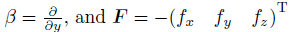
where Q = (u v w)T is the displacement vector,where u,v,and w are the total displacement components along x-,y-,and z- directions,respectively. P = (σxz σyz σzz)T is the stress vector,where σxz,σyz,and σzz are the transverse stresses. The superscript T denotes a matrix transposition. V is the considered volume. SA denotes the surface over the volume V . Bpq =
 )T,where pi (i = x,y,z) are the stress boundary
conditions in three coordinate directions.
)T,where pi (i = x,y,z) are the stress boundary
conditions in three coordinate directions.  denote the prescribed displacement
boundary conditions along x-,y-,and z- directions,respectively. Bpq =
denote the prescribed displacement
boundary conditions along x-,y-,and z- directions,respectively. Bpq =  T,
where pi (i = x,y,z) are the prescribed stress boundary conditions in the x-,y-,and z- directions,
respectively.
T,
where pi (i = x,y,z) are the prescribed stress boundary conditions in the x-,y-,and z- directions,
respectively.  are the
characteristic coefficients,where the value of
are the
characteristic coefficients,where the value of  is 1 or 0. = 1 and
= 0 denote the stress and displacement boundary cases in three coordinates
directions,respectively.
is 1 or 0. = 1 and
= 0 denote the stress and displacement boundary cases in three coordinates
directions,respectively.
The expression of H in (10) can be written as
where G1 =
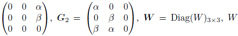 is a weight function,
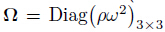 ,ρ is the unit density of a material,ω is the circular frequency,
 ,
,
 denotes the vector of body forces or external loading.
For the isotropic and orthotropic materials,
where

 are known as
the stiffness coefficients of a material.
are known as
the stiffness coefficients of a material.
By virtue of the LRPIM shape function,the stress vector P and the displacement vector Q at any one quadrature point can be expressed as follows:
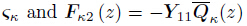
where
 and z is the thickness of the problem domain. The subscript “κ” denotes the variable of a
point.
and z is the thickness of the problem domain. The subscript “κ” denotes the variable of a
point.
Substituting (13) into (10) and applying the operations of variational calculus and integrating, the expression of the first term of (10) can be obtained as follows:
where where where Ωq is the local quadrature domain,Γ is the global boundary of surface SA,Γqi is the inner boundary of Ωq and is not intersect with Γ,Γqu is the part of the displacement boundary which intersects with Ωq,and Γqt is the part of the stress boundary which intersects with Ωq, VI1T and VI2T are matrices for the derivatives of the weight functions,WI is a matrix of weight functions,and n is a matrix for vectors of the unit outward normal on the boundary.


The boundary term can be expressed as the following form:
where

 dΓ,in which
and Λ0 = Diag(λx,λy,λz).
Adding (17) to the right hand side of (14),a LRPIM formula of the Hamilton canonical
equation for the local quadrature domain can be expressed as
where
dΓ,in which
and Λ0 = Diag(λx,λy,λz).
Adding (17) to the right hand side of (14),a LRPIM formula of the Hamilton canonical
equation for the local quadrature domain can be expressed as
where 

 are the
equivalent stiffness matrices for the local quadrature domain,
are the
equivalent stiffness matrices for the local quadrature domain,
 are the equivalent external load vectors for the local quadrature
domain.
2.3 Numerical implementation for LRPIM
are the equivalent external load vectors for the local quadrature
domain.
2.3 Numerical implementation for LRPIM
Gauss quadrature is used to evaluate the integrations in (14) and (17). The integrations are performed based on the local quadrature domains centered by field nodes. Obviously,more reasonable results can be obtained by using the weight function with the local property that decrease with increase in the distance between a point xQ and the node xi [40]. The following spline weight function which only depends on the distance between two points are employed in the present work:
where di = |xQ − xi| is the distance between the node xi and the integration point xQ,and rw is the size of the support for the weight function.
For each Gauss quadrature point xQ,the LRPIM shape functions are constructed to yield the integrand. For a field node xi,the local quadrature domain Ωq (size rq),the local weight function domain Ωw where wi ≠= 0 (size rw),and the local support domain Ωs for xQ (size rs) are introduced. These domains are arbitrary when the condition rq ≤ rw is satisfied. Since the spline weight function will be zero along the inner boundary Γqi when the sizes of local integration domain and weight domain are the same,rq = rw is adopted in the present work. rq and rs are respectively defined as rq = αqdci and rs = αsdci,where αq and αs are dimensionless sizes taken to control the real domain sizes,and dci is the shortest distance from the node xi to neighbor nodes.
Note that the LRPIM shape functions possess complex characteristics and different forms in each local integration region. Therefore,the derivatives of shape functions may have an oscillation. In addition,the sum of all local quadrature domains should cover the whole domain. The overlapping of interpolation domains results in the integrand in the overlapping domain is very complex. For the reasons above,Ωq should be cut into some regular smaller partitions so as to ensure the precision of the numerical integration[40]. 3 Meshfree modeling of delaminated laminate
The geometry of a laminated rectangular plate with a delamination is shown in Fig. 1. a,b, and h denote the length,width,and thickness of laminate,respectively. S denotes the area of delamination,and A denotes the area of the whole domain.
 |
| Fig. 1 Geometry of delaminated composite laminate |
By assembling the equivalent stiffness matrices and equivalent external load vectors of local quadrature domain,the LRPIM formula of the Hamilton canonical equation for a layer with n nodes can be obtained as follows:
where
 is the
transverse stress vector,
is the
transverse stress vector, is the
displacement vector,
is the
displacement vector,
 is the state variable,A12 and A21 are the equivalent stiffness
matrices for the whole domain,Fp (z) =
is the state variable,A12 and A21 are the equivalent stiffness
matrices for the whole domain,Fp (z) =  and Fq (z) =
 are the equivalent external load vectors for the whole domain.
The exact solution to (21) of the μth sublaminate can be expressed by
where where Pμ(hμ) and Qμ(hμ) are the stress and displacement vectors,respectively,relative to the bottom surface of the μth sublaminate. Pμ(0) and Qμ(0) are the stress and displacement vectors,respectively,relative to the top surface of the μth sublaminate. hμ is the thickness of the μth sublaminate.

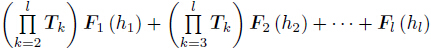
Based on the transfer matrix technique,which takes use of the interlaminar displacement and stress compatibility conditions,i.e.,the state variables of the two surfaces are regarded as the same,the recurrence formulation of a laminate with l-layer is
where hk (k = 1,2,· · · ,l) is the thickness of each layer.
(24) is the governing equation of an l-layer composite laminate. It can be recast into a matrix form as follows:
where
 are state variables in the bottom and top surfaces
of the laminate with l-layer.
are state variables in the bottom and top surfaces
of the laminate with l-layer. is the equivalent stiffness matrix,and
 is the equivalent external load vector.
Applying the procedure above to the upper and lower sublaminates,respectively,two control
equations which are similar to (25) can be obtained. For convenience,the following expressions
with superscripts are used to express the control equations of upper and lower sublaminates.
For the upper sublaminate,
and for the lower sublaminate,
where superscripts “bu” and “tu” denote the bottom and top surfaces of upper sublaminate,
respectively,while superscripts “bl” and “tl” denote the bottom and top surfaces of lower
sublaminate,respectively.
3.2 Spring layer model
is the equivalent external load vector.
Applying the procedure above to the upper and lower sublaminates,respectively,two control
equations which are similar to (25) can be obtained. For convenience,the following expressions
with superscripts are used to express the control equations of upper and lower sublaminates.
For the upper sublaminate,
and for the lower sublaminate,
where superscripts “bu” and “tu” denote the bottom and top surfaces of upper sublaminate,
respectively,while superscripts “bl” and “tl” denote the bottom and top surfaces of lower
sublaminate,respectively.
3.2 Spring layer model

The spring layer model,which is similar to that used in Refs. [26, 27, 28, 33, 34, 35],is employed to describe the bonding conditions between upper and lower sublaminate:
where
 denote the out-of-plane stresses of top surface of
lower sublaminate and bottom surface of upper sublaminate.
denote the out-of-plane stresses of top surface of
lower sublaminate and bottom surface of upper sublaminate.  denote the displacements of top surface of lower sublaminate and the bottom surface of upper
sublaminate.
denote the displacements of top surface of lower sublaminate and the bottom surface of upper
sublaminate.  are three bonding stiffness constants in the x-,y-,and z- directions,
respectively. Obviously,the displacements will be continuous across the interface
when Ki
are three bonding stiffness constants in the x-,y-,and z- directions,
respectively. Obviously,the displacements will be continuous across the interface
when Ki  ,which implies a perfect bonding. While
  indicates
that the upper sublaminate and the lower sublaminate are completely delaminated from each
other. For the ’constrained mode’,
indicates
that the upper sublaminate and the lower sublaminate are completely delaminated from each
other. For the ’constrained mode’, . While for the “free mode”,
 .
.
For the “free mode”,to prevent interpenetration phenomenon between delaminated sublaminates in the delaminated region,a unilateral frictionless contact interface characterized by a zero stiffness for opening relative displacements (Δw ≠ 0) and a positive stiffness for closing relative displacements (Δw < 0) can be introduced,which can be expressed as follows:
where “sign” is the signum function.
Assuming that the FEM background cells scheme used in spring layer with n field nodes is the same as that used in each layer of sublaminates,the matrix form of (28) can be expressed as
where Ptl denotes the transverse stress vector of the top surface of lower sublaminate,Pbu denotes the transverse stress vector of the bottom surface of upper sublaminate,Qtl denotes the displacement vector of the top surface of lower sublaminate,Qbu denotes the displacement vector of the bottom surface of upper sublaminate,


 are the dimensionless
compliance coefficients of the interfaces,where
are the dimensionless
compliance coefficients of the interfaces,where  is an elastic coefficient of the first lamina,
 are the shear modulus,elastic
modulus,and Poisson’s ratio of the first lamina,respectively. In the present computing
program,the numerical instabilities can be avoided by the following values of dimensionless
compliance coefficients. In the delaminated region,for the “constrained mode”,Rx = Ry = 108
and Rz = 0,while for the “free mode”,Rx = Ry = Rz = 108. In the undelaminated region,
Rx = Ry = Rz = 0.
3.3 Vibration analysis of laminate with delamination
are the shear modulus,elastic
modulus,and Poisson’s ratio of the first lamina,respectively. In the present computing
program,the numerical instabilities can be avoided by the following values of dimensionless
compliance coefficients. In the delaminated region,for the “constrained mode”,Rx = Ry = 108
and Rz = 0,while for the “free mode”,Rx = Ry = Rz = 108. In the undelaminated region,
Rx = Ry = Rz = 0.
3.3 Vibration analysis of laminate with delamination
Substituting (30) into (27),the following expression can be obtained:

Eliminating the vector Pbu Qbu )T by (26),the final governing equation can be obtained as follows:
where is the equivalent stiffness matrix of the laminate with delamination where Θp and Θq are the equivalent body force vectors.


For the undamped free vibration analysis of delaminated laminated plates,the equivalent body force vectors vanish from (33),and then the final governing equation can be expressed as follows:

Considering that the top surface and bottom surface are stress free,i.e.,the stress vectors Pbl = Ptu = 0. The governing equation for undamped free vibration analyses can be deduced from (36),which can be expressed as follows:

The determinant condition that Qtu = 0 exists nonzero solution is that B12 is a singular matrix. Thus,the eigenpolynomial must be zero,namely,

The frequencies ω can be solved from (38). Note that the elements in matrix B12 are the transcendental functions of the frequencies. This is a nonlinear eigenvalue problem,and the iteration methods should be used to solve this problem. In this paper,the Newton-Raphson method is used to obtain the required eigenvalues. 4 Numerical examples and discussion
To demonstrate the accuracy and effectiveness of the present model,four examples were resolved. Numerical results of the free vibration frequency and mode shape are obtained and compared with existing results reported in Refs. [7, 8, 9, 10, 11, 12, 13, 17].
Typical RBFs include the multi-quadrics (MQ) function,the Gaussian (GAU) function,the thin plate spline (TPS) function and the Logarithmic (LOG) function,which are respectively defined as follows:
where ri is the distance from the point of interest x to a node at xi,αc,q,and η are dimensionless shape parameters,and dc is a characteristic length relevant to the nodal spacing in the local support domain of x. The shape parameters should be determined for different problems. For example,in the MQ function,two shape parameters,i.e.,αc and q,need to be determined firstly. Liu and Gu[41] pointed out that,for solid and fluid mechanics,satisfactory results can be obtained when q = 0.98 or 1.03. In the present examples,the MQ function is adopted,and q = 0.98 and αc = 0.03 are taken.
The rectangular quadrature domain is employed in the following examples,and the dimension of the quadrature domain can be determined by rqx = αqxdcx and rqy = αqydcy in the xand y-directions,respectively,where αqx and αqy are dimensionless quadrature domain sizes respectively in x- and y-directions,and dcx and dcy are the shortest nodal spacings respectively in the x- and y-directions. αqx = αqy = 2 is taken in the following examples. 4.1 Vibration of laminated beams with central delamination
The cantilever eight-layer laminated beam with a [0/90]2s stacking sequence is taken for comparison purpose. The geometry of delaminated beam and the locations of delaminations are referred to Ref. [7]. The material properties of the beam (each layer) which is made of T300/934 graphite/epoxy are E11 = 134GPa,E22 = 10.3GPa,G12 = 5GPa,ν12 = 0.33,and ρ = 1.48 × 10³ kg · m−3. All the layers have the same thickness and the dimensions of the beam are a×b×h = (127×12.7×1.016)mm3. The lengths of the delaminations are 25.4 mm, 50.8mm,76.2mm,and 101.6mm,respectively,and the interface location of delaminations is shown in Fig. 2.
 |
| Fig. 2 Interface location of delaminations |
In this example,the whole beam in the xy-plane is discretized by 306 field nodes (51 × 6), which are uniformly distributed for convenience of programming and calculation. For Gauss quadrature,the 8×8 quadrature scheme (i.e.,64 Gauss points in each regular smaller partition of local quadrature domain) is employed to evaluate local domain integrals. Fundamental frequencies of the beam with delamination located at Interfaces 1-4 are compared respectively in Tables 1-4 for both “free mode” and “constrained mode”.
 |
 |
 |
 |
It can be seen that the present results agree well with the analytical and experimental results[7, 8, 12] (except at Interface 4) and finite element results[9]. The exception in experimental results at Interface 4 might be an experimental error. It can be found that the fundamental frequencies decrease with the increase in the delamination length,which indicates that the stiffness of delaminated beam decreases with the increase in the delamination length. In addition, the fundamental frequencies increase with the increase in the number of interface where the dealmination is located,which means that the stiffness of delaminated beam decreases even more when the delamination is closer to midplane.
The second and third frequencies of the laminated beam with delamination centrally located at Interfaces 1 are compared in Tables 5-6 for both “free mode” and “constrained mode”.
 |
 |
Good agreement can also be found between the present results and those obtained by using analytical model[12],finite element models based on the high order theory and 3D NASTRAN analysis[10]. From Tables 1-6,it can be seen that the frequencies for “free mode” are smaller than those for “constrained mode”,and this is less obvious when the location of delamination is closer to midplane. The results for the two modes are almost identical when the delamination is located at midplane. 4.2 Vibration of laminated beams with two non-central delaminations
The cantilever laminated beam with two non-overlapping delaminations studied by Shu and Della[11] is taken for a comparison purpose. The schematic diagram of the beam with length a and thickness h is shown in Fig. 3. The two non-overlapping delaminations with lengths a1 and a2 are located at distances d1 and d2 from the center of the beam,respectively. The geometry and material of beam are identical to those of the beam discussed in Subsection 4.1. Four cases of the delamination locations are taken into account and defined as follows:
 |
| Fig. 3 Cantilever laminated beam with two non-overlapping delaminations |
Case 1 Symmetric midplane delaminations: h1 = h2 = 0.5h.
Case 2 Symmetric delaminations: h1 = h2 = 0.375h.
Anti-symmetric delaminations: h1 = 0.625h,h2 = 0.375h.
Case 3 Symmetric delaminations: h1 = h2 = 0.25h.
Anti-symmetric delaminations: h1 = 0.75h,h2 = 0.25h.
Case 4 Symmetric delaminations: h1 = h2 = 0.125h.
Anti-symmetric delaminations: h1 = 0.875h,h2 = 0.125h.
In this example,the discrete method and quadrature scheme are the same as those used in Subsection 4.1. The fundamental frequencies of the beam for the four cases are presented and compared in Tables 7-10.
 |
 |
 |
 |
Good agreement can be observed between the present results and those obtained by Shu and Della[11]. The presence of two delaminations significantly decreases the frequency of the beam. It can be found that the frequencies of a beam with symmetric delaminations or anti-symmetric delaminations are almost identical (Cases 2-4). In addition,there is a little difference between the frequencies of the beam with the delaminations located at d1 = d2 = 0.25a and d1 = d2 = 0.45a− a1/2 ,that is,close to the beam ends. This indicates that the fundamental frequencies decrease as the delamination is closer to the fixed end of beam. From Tables 7-10,it can also be seen that the frequencies for “free mode” are smaller than those for “constrained mode”, and this is less obvious when the location of delamination is closer to midplane. The results for the two modes are also identical when the delamination is located at midplane (Case 1). 4.3 Vibration of laminated plates with a central delamination
The eight-layer square laminated plate with a square delamination located at the center of the midplane studied by Ju et al.[13] is taken for a comparison purpose. The size of the laminated plate with a [0/90/45/90]s stacking sequence is a × b × h,where a = b = 250mm and h = 2.12mm. The material properties of the laminated plate are: E11 = 132GPa,E22 = 5.35GPa,G12 = G13 = 2.79GPa,ν12 = ν13 = 0.291,ν23 = 0.3,and ρ = 1 446.2 kg · m−3. Four kinds of typical boundary conditions,i.e.,four edges free (FFFF),four edges simply supported (SSSS),four edges clamped (CCCC),and cantilevered (CFFF),are taken into account.
In this example,the whole plate in the xy-plane is discretized by 289 field nodes (17 × 17),which are uniformly distributed for convenience of programming and calculation. The quadrature scheme is the same as that used in Sections 4.1 and 4.2. Based on the “free mode”, the first six natural frequencies of the plate for two delamination conditions,in which the side lengths are respectively a/3 and a/2,are obtained and compared in Table 11. fi (i = 1,2,· · · ,6) denote the frequencies 1-6 of the plate.
 |
Good agreement can be observed between the present results and that obtained by Ju et al.[13]. It can be found that the influence of delamination size on natural frequencies is strongly related to the boundary conditions. For the CFFF and FFFF boundary conditions, the frequencies decrease slowly even when the delamination area is a quarter of the total plate area,and in contrast,they decrease greatly for the SSSS and CCCC boundary conditions. In addition,the reduction of frequency due to the presence of delamination is more obvious for higher modes. The first six mode shapes of a CCCC intact plate and the plate with a delamination whose side length is a/3 are compared in Figs. 4-5. mi (i = 1,2,· · · ,6) denote the mode shapes of the intact plate,and mid (i = 1,2,· · · ,6) denote the mode shapes of the delaminated plate. It shows that the obvious bending deformation can be found in the fifth and sixth mode shapes,which indicates that the higher mode shapes are more easily influenced by delamination. There may be an impact between the upper and lower sublaminates in the delaminated region during the vibration,which can lead to variations of energy dissipation. It can be seen that this phenomenon is modal dependent,and therefore,the delamination can be detected by the variation of mode shapes.
 |
| Fig. 4 Mode shapes 1-3 of CCCC square intact composite plate and those with central delamination |
 |
| Fig. 5 Mode shapes 4-6 of CCCC square intact composite plate and those with central delamination |
The eight-layer FFFF square laminated plate with a square delamination studied by Alnefaie et al.[17] is taken for a comparison purpose. The size of the laminated plate with a [0/90/0/90]s stacking sequence is a × b × h,where a = b = 225.5 mm and h = 2.05 mm. The material properties of the laminated plate are E11 = 37.78 GPa,E22 = E33 = 10.9 GPa,G12 = G13 = G23 = 4.91 GPa,ν12 = ν13 = 0.3,ν23 = 0.11,and ρ = 1 813.9 kg · m−3. The location of the delamination is between the third and the fourth layers counting from the top of the plate and the coordinates of delamination center are x = y = 163.5 mm and z = 1.281 25mm. Four side lengths of delamination,i.e.,11.275mm,33.825mm,56.375mm,and 78.925 mm are considered.
In this example,the discrete method and quadrature scheme are the same as those used in Subsection 4.3. Based on the “free mode”,the first nine natural frequencies of the delaminated plate are obtained and compared in Table 12. fi (i = 1,2,· · · ,9) denote the frequencies 1-9 of the plate.
 |
Good agreement can be observed between the present results and those obtained by Alnefaie et al.[17]. It can be found that the frequencies decrease as the delamination size increases,and the reductions of frequencies due to the presence of delamination are very small for the first six modes and higher for the other modes.
The first nine mode shapes of intact plate and the plate with a delamination whose side length is 56.375 mm are compared in Figs. 6-8. mi (i = 1,2,· · · ,9) denote the mode shapes of intact plate,and mid (i = 1,2,· · · ,9) denote the mode shapes of delaminated plate. It shows that the obvious bending deformation can be found in the seventh,eighth and ninth mode shapes,and this also indicates that the higher mode shapes are more easily influenced by delamination.
 |
| Fig. 6 Mode shapes 1-3 of FFFF square composite plate and those with non-central delamination |
 |
| Fig. 7 Mode shapes 4-6 of FFFF square composite plate and those with non-central delamination |
 |
| Fig. 8 Mode shapes 7-9 of FFFF square composite plate and those with non-central delamination |
The free vibration frequencies and mode shapes of delaminated composite beams and plates have been studied based on a meshfree semi-analytical model. A hybrid governing equation for vibration analysis of the composite laminates with delaminations is deduced using the LRPIMin Hamilton system. The present solution accounts for transverse shear deformation and rotatory inertia. The advantage of this approach is that the numerical errors and field nodes do not increase with the thickness or layer numbers. Numerical results are in good agreement with existing results,and the following conclusions can be extracted from the present work.
The frequencies decrease as the number of delaminations increases,and the reduction of frequency is related to boundary conditions and modes. In addition,the frequencies decrease even more when the location of delamination is closer to midplane. The frequencies for “free mode” are smaller than those for “constrained mode”,and this is less obvious when the location of delamination is closer to midplane. The influence of delamination can be seen more directly and clearly,and the changes of mode shapes are mode-dependent. The higher mode shapes are more easily influenced by delamination.
| [1] | Ramkumar, R. L., Kulkarni, S. V., and Pipes, R. B. Free vibration frequencies of a delaminated beam. Proceedings of 34th Annual Technical Conference, Reinforced/Composite Institute, Society of Plastics Industry, 1-5 (1979) |
| [2] | Wang, J. T. S., Liu, Y. Y., and Gibby, J. A. Vibrations of split beams. Journal of Sound and Vibration, 84(4), 491-502 (1982) |
| [3] | Mujumdar, P. M., and Suryanarayan, S. Flexural vibrations of beams with delaminations. Journal of Sound and Vibration, 125(3), 441-461 (1988) |
| [4] | Zou, Y., Tong, L. P. S. G., and Steven, G. P. Vibration-based model-dependent damage (delamination) identification and health monitoring for composite structures鈥攁 review. Journal of Sound and Vibration, 230(2), 357-378 (2000) |
| [5] | Hou, J. P. and Jeronimidis, G. Vibration of delaminated thin composite plates. Composites Part A: Applied Science and Manufacturing, 30(8), 989-995 (1999) |
| [6] | Della, C. N., and Shu, D. Vibration of delaminated composite laminates: a review. Applied Mechanics Reviews, 60(1), 1-20 (2007) |
| [7] | Shen, M. H. and Grady, J. E. Free vibrations of delaminated beams. AIAA Journal, 30(5), 1361-1370 (1992) |
| [8] | Luo, H. and Hanagud, S. Dynamics of delaminated beams. International Journal of Solids and Structures, 37(10), 1501-1519 (2000) |
| [9] | Hu, N., Fukunaga, H., Kameyama, M., Aramaki, Y., and Chang, F. K. Vibration analysis of delaminated composite beams and plates using a higher-order finite element. International Journal of Mechanical Sciences, 44(7), 1479-1503 (2002) |
| [10] | Radu, A. G. and Chattopadhyay, A. Dynamic stability analysis of composite plates including delaminations using a higher order theory and transformation matrix approach. International Journal of Solids and Structures, 39(7), 1949-1965 (2002) |
| [11] | Shu, D. and Della, C. N. Free vibration analysis of composite beams with two non-overlapping delaminations. International Journal of Mechanical Sciences, 46(4), 509-526 (2004) |
| [12] | Della, C. N. and Shu, D. Free vibration analysis of composite beams with overlapping delaminations. European Journal of Mechanics-A/Solids, 24(3), 491-503 (2005) |
| [13] | Ju, F., Lee, H. P., and Lee, K. H. Finite element analysis of free vibration of delaminated composite plates. Composites Engineering, 5(2), 195-209 (1995) |
| [14] | Lee, J. Free vibration analysis of delaminated composite beams. Computers & Structures, 74, 121-129 (2000) |
| [15] | Ramtekkar, G. S. Free vibration analysis of delaminated beams using mixed finite element model. Journal of Sound and Vibration, 328(4), 428-440 (2009) |
| [16] | Gallego, A., Moreno-Garc a, P., and Casanova, C. F. Modal analysis of delaminated composite plates using the finite element method and damage detection via combined Ritz/2D-wavelet analysis. Journal of Sound and Vibration, 332(12), 2971-2983 (2013) |
| [17] | Alnefaie, K. Finite element modeling of composite plates with internal delamination. Composite Structures, 90, 21-27 (2009) |
| [18] | Kargarnovin, M. H., Ahmadian, M. T., Jafari-Talookolaei, R. A., and Abedi, M. Semi-analytical solution for the free vibration analysis of generally laminated composite Timoshenko beams with single delamination. Composites Part B: Engineering, 45(1), 587-600 (2013) |
| [19] | Marjanović, M., and Vuksanović, D. Layerwise solution of free vibrations and buckling of laminated composite and sandwich plates with embedded delaminations. Composite Structures, 108, 9-20 (2014) |
| [20] | Bahar, L. Y. A state space approach to elasticity. Journal of the Franklin Institute, 299(1), 33-41 (1975) |
| [21] | Chandrashekara, S. and Santhoshi, U. Natural frequencies of cross-ply laminates by state space approach. Journal of Sound and Vibration, 136(3), 413-424 (1990) |
| [22] | Fan, J. R. and Ye, J. Q. An exact solution for the statics and dynamics of laminated thick plates with orthotropic layers. International Journal of Solids and Structures, 26(5), 655-662 (1990) |
| [23] | Steele, C. R. and Kim, Y. Y. Modified mixed variational principle and the state-vector equation for elastic bodies and shells of revolution. Journal of Applied Mechanics, 59(3), 587-595 (1992) |
| [24] | Ouyang, H. J. and Zhong, W. X. Hamiltonian system and simpletic geometry in mechanics of materials (III)鈥攆lexure and free vibration of plates. Applied Mathematics and Mechanics (English Edition), 14(1), 21-25 (1993) DOI 10.1007/BF02451217 |
| [25] | Zou, G. P. and Tan, L. M. A semi-analytical solution for thermal stress analysis of laminated composite plates in the Hamiltonian system. Computers & Structures, 55(1), 113-118 (1995) |
| [26] | Chen, W. Q. and Lee, K. Y. Three-dimensional exact analysis of angle-ply laminates in cylindrical bending with interfacial damage via state-space method. Composite Structures, 64, 275-283 (2004) |
| [27] | Chen,W. Q., Cai, J. B., Ye, G. R., andWang, Y. F. Exact three-dimensional solutions of laminated orthotropic piezoelectric rectangular plates featuring interlaminar bonding imperfections modeled by a general spring layer. International Journal of Solids and Structures, 41(18), 5247-5263 (2004) |
| [28] | Chen, W. Q., Jung, J. P., and Lee, K. Y. Static and dynamic behavior of simply-supported crossply laminated piezoelectric cylindrical panels with imperfect bonding. Composite Structures, 74, 265-276 (2006) |
| [29] | Qing, G. H., Qiu, J. J., and Liu, Y. H. Modified HR mixed variational principle for magnetoelectroelastic bodies and state-vector equation. Applied Mathematics and Mechanics (English Edition), 26(6), 722-728 (2005) DOI 10.1007/BF02465422 |
| [30] | Qing, G. H., Qiu, J. J., and Liu, Y. H. Free vibration analysis of stiffened laminated plates. International Journal of Solids and Structures, 43(6), 1357-1371 (2006) |
| [31] | Qing, G. H., Qiu, J. J., and Liu, Y. H. Hamiltonian parametric element and semi-analytical solution for smart laminated plates. Applied Mathematics and Mechanics (English Edition), 28(1), 51-58 (2007) DOI 10.1007/s10483-007-0106-z |
| [32] | Qing, G. H., Xu, J. X., and Qiu, J. J. State-vector equation with damping and vibration analysis of laminates. Applied Mathematics and Mechanics (English Edition), 28(2), 253-259 (2007) DOI 10.1007/s10483-007-0214-1 |
| [33] | Qing, G. H., Liu, Y. H., and Li, D. H. A semi-analytical model for the energy release rate analyses of composite laminates with a delamination. Finite Elements in Analysis and Design, 47(9), 1017-1024 (2011) |
| [34] | Qing, G. H., Wang, F. X., and Liu, Y. H. State-space approach for energy release rate analysis of delaminated laminates with stiffeners. AIAA Journal, 49(10), 2123-2129 (2011) |
| [35] | Li, D. H. and Qing, G. H. Free vibration analysis of composite laminates with delamination based on state space theory. Mechanics of Advanced Materials and Structures, 21, 402-411 (2014) |
| [36] | Belytschko, T., Lu, Y. Y., and Gu, L. Element-free Galerkin methods. International Journal for Numerical Methods in Engineering, 37(2), 229-256 (1994) |
| [37] | Belytschko, T., Krongauz, Y., Organ, D., Fleming, M., and Krysl, P. Meshless methods: an overview and recent developments. Computer Methods in Applied Mechanics and Engineering, 139(1), 3-47 (1996) |
| [38] | Atluri, S. N. and Zhu, T. A new meshless local Petrov-Galerkin (MLPG) approach in computational mechanics. Computational Mechanics, 22(2), 117-127 (1998) |
| [39] | Liu, G. R., Yan, L., Wang, J. G., and Gu, Y. T. Point interpolation method based on local residual formulation using radial basis functions. Structural Engineering and Mechanics, 14(6), 713-732 (2002) |
| [40] | Liu, G. R. and Gu, Y. T. A local radial point interpolation method (LRPIM) for free vibration analyses of 2-D solids. Journal of Sound and Vibration, 246(1), 29-46 (2001) |
| [41] | Liu, G. R. and Gu, Y. T. An Introduction to Meshfree Methods and Their Programming, Springer, Netherlands (2005) |
| [42] | Xiong, Y. B. and Long, S. Y. Local Petrov-Galerkin method for a thin plate. Applied Mathematics and Mechanics (English Edition), 25(2), 210-218 (2004) DOI 10.1007/BF02437322 |
| [43] | Zeng, Q. H. and Lu, D. T. Galerkin meshless methods based on partition of unity quadrature. Applied Mathematics and Mechanics (English Edition), 26(7), 893-899 (2005) DOI 10.1007/s10483-006-0709-z |
| [44] | Liu, G. L. and Li, X. W. Mesh free method based on local cartesian frame. Applied Mathematics and Mechanics (English Edition), 27(1), 1-6 (2006) DOI 10.1007/s10483-006-0101-1 |
| [45] | Li, D. H., Xu, J. X., and Qing, G. H. Free vibration analysis and eigenvalues sensitivity analysis for the composite laminates with interfacial imperfection. Composites Part B: Engineering, 42(6), 1588-1595 (2011) |
| [46] | Li, D. H. and Liu, Y. Three-dimensional semi-analytical model for the static response and sensitivity analysis of the composite stiffened laminated plate with interfacial imperfections. Composite Structures, 94(6), 1943-1958 (2012) |