 2016, Vol. 37
Article Information
- Liyuan ZHANG, Cheng ZHANG, Xiqiao FENG, Huajian GAO. 2016.
- Snapping instability in prismatic tensegrities under torsion
- Appl. Math. Mech. -Engl. Ed., 37(3): 275-288
- http://dx.doi.org/10.1007/s10483-016-2040-6
Article History
- Received Jun. 25, 2015;
- in final form Aug. 30, 2015


2. AML & CNMM, Department of Engineering Mechanics, Tsinghua University, Beijing 100084, China;
3. School of Engineering, Brown University, Providence, Rhode Island 02912, U.S.A.
Tensegrities are lightweight spatial structures consisting of strings and bars connected by ball joints. Due to the unique mechanical characteristics with/without loads[1, 2], tensegrities hold various applications in the design of civil architectures[3], smart devices[4], advanced materials[5], biomechanical models[6], etc.
Tensegrities can hold self-equilibrated states with no external load and constraint when the pre-tensions of the strings and the pre-compressions of bars satisfy the self-equilibrium condi-tions. Some analytical and numerical methods have been developed for the form-finding or self-equilibrium analyses of tensegrities[7, 8, 9]. Using these methods, researchers have designed various types of tensegrities[10, 11, 12]. It is found that some of them can have multiple self-equilibrated and stable states[13, 14, 15, 16, 17].
A major concern in the practical applications of tensegrities is the evaluation of their mechanical responses to external stimuli. In comparison with conventional truss structures, tensegrities may undergo much larger rotations of elements, inducing significant geometric non-linearity[18, 19]. Clustered tensegrities are used as sensing and actuating structures because of their capability of large deformation in all directions[20, 21, 22, 23]. Numerical methods are the general means to simulate the non-linear behaviors of the tensegrities under various loading conditions[24, 25, 26, 27], while analytical solutions usually involve the assumptions of the structural symmetry and rigid elements to reduce the unknown variables[28, 29, 30].
For a tensegrity with multiple stable states, applying certain loads to one stable state may trigger its transformation to another. Defossez[13] applied random external nodal forces to actuate the state transformations of a tensegrity with 6 bars and 24 strings and a tensegrity with 30 bars and 90 strings, respectively. Xu and Luo[15] explored the actuations and thresholds to transform a tensegrity with 6 bars and 24 strings between its three stable configurations. In the transformation process, the externally equilibrated loads firstly increased from 0 to a certain value, and then decreased back to 0. Structural instability may occur in this purely elastic deformation. However, the snapping instability behavior of tensegrities has not been uncovered.
Snapping instability refers to a transition between two stable states in a structure. This kind of instability has been reported in the deformation responses of elastic beams, arches, and shells[31, 32, 33]. These phenomena may cause structural failure in some cases[34, 35], but they may also been exploited to actuate switches[36] or absorb vibrations[37]. The tensegrities with snapping instability hold potential applications in the design of advanced devices and systems with prominent functions.
The present study focuses on the mechanical responses, in particular the snapping instability, of the prismatic tensegrities subjected to the torsion about the prismatic axis. The paper is organized as follows. Section 2 analyzes the possible equilibrated states of a prismatic tensegrity in the absence of external loads. Section 3 derives the formulation of the mechanical responses of the prismatic tensegrities under the torsion. Several representative examples are provided in Section 4 to demonstrate the specific snapping instability behavior. Section 5 presents an experiment validation of the theoretical results.
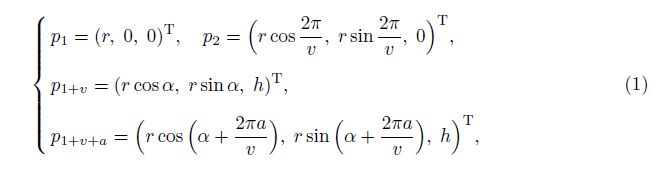
2 Self-equilibrium analysisPrismatic tensegrities are a class of three-dimensional tensegrity structures (see Fig. 1(a)). A regular v-prismatic tensegrity consists of 2v nodes, 2v end strings, v side strings, and v bars. All elements of the same type are assumed to have identical length and mechanical properties. The end strings form the bottom polygon and the top polygon, and the side strings and bars link the bottom and the top. Figure 1(b) illustrates several representative nodes and elements in a v-prismatic tensegrity, in which an end string connects Nodes 1 and 2, a side string connects Nodes 1 and 1 + v, and a bar connects Nodes 1 and 1 + v + a, where a is a positive integer smaller than v. α is the twist angle of the top polygon with respect to the bottom polygon. When all side strings are parallel to the vertical direction, α = 0. h denotes the height of the structure, and r is the radius of the circumscribed circle.
2.1 Geometry and potential energyRefer to the Cartesian coordinate system (O-xyz) in Fig. 1(b). The coordinates of Nodes 1, 2, 1 + v, and 1 + v + a are


|
| Fig. 1 Prismatic tensegrities |
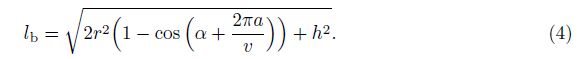
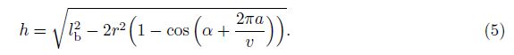
Generally, the bars are much stiffer than the strings, and thus can be assumed to be rigid. Here, we focus on the case when all end strings are also relatively inextensible and can bear both tension and compression, forming two rigid plates at the top and the bottom surfaces[5, 29]. Thus, the values of lb, les, and r are specified to be constant during the structural deformation analysis. Then, the structural height can be solved by Eq. (4) as follows:

For the present problem, the total potential energy of the structure is just the sum of the elastic strain energies in all side strings, i.e.,
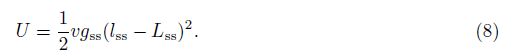
In the absence of an external load, a tensegrity will be in self-equilibrium when its potential energy has a local extreme value, i.e.,
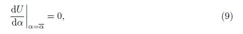
Substituting Eq. (8) into Eq. (9) yields
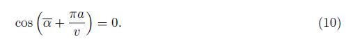
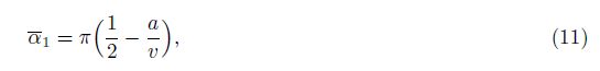
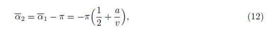
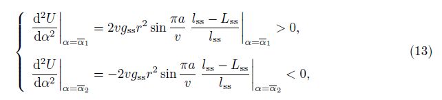
So far, only the first self-equilibrated state of the prismatic tensegrities with the twisting angle α = α1 has been emphasized in the literature[29, 38], due to the constraining end strings in the tension. However, our usage of the rigid surfaces at the two ends allows the prismatic tensegrity to have a second self-equilibrated configuration where α = α2. Furthermore, the total potential energy of the structure is minimized at the first self-equilibrated state and is maximized at the second self-equilibrate state, since
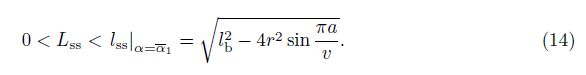
In addition, the minimum energy at the first state indicates the side strings at their shortest length among all possible states of the structure with or without external loads. All side strings are in the tension of this state, and can be confirmed by
Generally, the self-equilibrated and stable state of the prismatic tensegrity, where α = α1, serves as the initial configuration before the application of an external load. In the following analysis, we focus on the right-handed prismatic tensegrities, where α1 > 0 (1≤a≤v/2), since the properties of the left-handed prismatic tensegrities are similar.
3 Mechanical responseFor clarity, we fix the bottom surface of a prismatic tensegrity and apply a torque at the top surface about the prismatic axis (see Fig. 2). To quantify the rotational deformation of the structure, the rotating angle θ is defined by


|
| Fig. 2 3-prismatic tensegrity subjected to torsional loading about its axis |

|
| Fig. 3 Configurations of 3-prismatic tensegrity at different θ |
With the deformation of a prismatic tensegrity, the originally unconnected bars or side strings may get in contact with each other at a certain value of angle θ[19, 29], giving rise to a constraint on the deformation range of the structure.
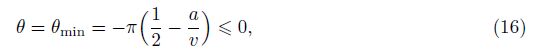
If a negative rotating angle θ is applied on the structure, all rigid bars will interfere with each other at the critical state, where
For a positive rotating angle θ, the interference of the side strings will occur when
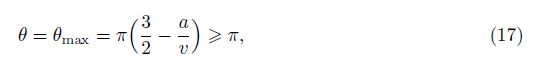
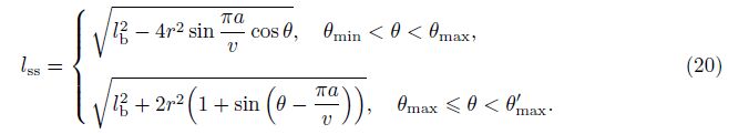
In contrast to the rigid bars, each flexible side string can deform from the original straight line to two connecting non-collinear lines (see Fig. 3(e)). Thus, the structure is allowed to have further deformation from the state, where θ = θmax, until all the rigid bars interfere again at
Therefore, the rotating angle of a prismatic tensegrity under torsion is confined in the ranges θmin < θ < θmax (without any intersection of elements) and θmax≤θ < θ'max (with the intersection of the side strings). For illustration, the configurations of a deformed 3-prismatic tensegrity, where θ = θmin = -π/6, θ = θmax = 7π/6, and θ = θ'max = 11π/6, are shown in Figs. 3(a), 3(d), and 3(f), respectively. When θ = θmin = -π/6, all bars intersect at the structure center. When θ = θmax = 7π/6, all side strings get in contact with each other at the structure center. When θ = θ'max = 11π/6, all bars and side strings intersect each other, and each side string kinks from an original straight line into two non-collinear segments with the connecting point at the structure center.
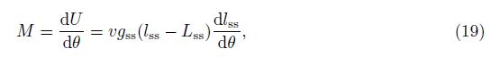
3.2 Load-deformation relationFor a prismatic tensegrity under torsion, the relation between the torque M and the rotating angle θ (θmin < θ < θ'max) can be obtained from the strain energy as follows:
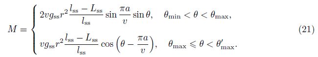
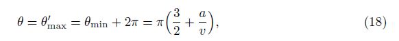
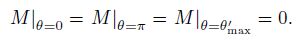
It is clear from Eq. (21) that the external load M has three states of zero value, i.e.,
Simulating the mechanical responses of the prismatic tensegrities under the torsion by use of the formulation in Subsection 3.2, we can find that the structural deformation properties have several universal features as follows:
(i) In the deformation range θmin≤θ < 0, the torque M decreases with the decrease in the rotating angle θ, and the minimum of M occurs at the state where θ = θmin whose value can be -∞.
(ii) In the range 0≤θ≤π, the torque M first increases from 0 and then decreases to 0 with the increase in θ. Therefore, the maximum value of M exists in this interval.
(iii) In the range π < θ≤θ'max, the torque M first decreases from 0, and then increases with the increase in θ. The maximum of M occurs at the state where θ = θ'max, and the value can be +∞.
There is also one distinct feature among the structural responses. The minimum value of the torque M in the range π < θ≤θ'max has two possible cases. In the first case, the minimum of M emerges at the state where θ is larger than θmax when the side strings have touched each other. In the second case, the minimum of M corresponds to θ smaller than θmax, emerging without the intersection of the side strings. Based on this difference, the structural deformation properties can be divided into two groups, and the corresponding examples will be given in Section 4.
In summary, the above investigation shows that a prismatic tensegrity structure subjected to the torsional loadings holds three equilibrated states with no torque in the deformation range θmin≤θ≤θ'max. The first two states are stable, and the third state is unstable. When the structure is clamped by increasing/decreasing the rotating angle, its configuration will deform continuously, and the curve of M-θ will be captured by Eq. (21). However, snapping instability will occur if the structural transformation is actuated by an applied torque (see the following sections).
4 Snapping instabilityBased on the theoretical results in Section 3, we design two representative prismatic tenseg-rities with the snapping instability under the torsional deformation. The structural deformation is actuated by applying a rotating angle and the associated torque about the prismatic axis. In the following analysis, all lengths and torques are normalized by r and gssr2, respectively, and the dimensionless parameters are marked by an overbar.
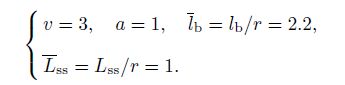
4.1 Deformation behavior of Structure-1We select a 3-prismatic tensegrity as Structure-1, whose parameters are set to be

|
| Fig. 4 Normalized torque M = M/(gssr2) versus rotating angle θ for prismatic tensegrity Structure-1 subjected to loadings via imposed rotating angle, applied torque starting at θ = 0, and applied torque starting at θ = θ'max |
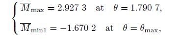
From Fig. 4, we can see that the structure exhibits snapping instability when M is larger than Mmax (see Fig. 4(b)) or smaller than Mmin2 (see Fig. 4(c)). During the deformation actuated by a rotating angle θ, the structural configuration changes continuously. The corresponding load-deformation curve is shown in Fig. 4(a). When θ decreases from 0 to θmin = -π/6, the torque M decreases monotonically from 0 to -0.682 7, and finally to -∞. However, when θ increases from 0 to θmax = 7π/6, the variation of M has two stages, increasing with the increase in θ in the value range from 0 to 1.790 7 and decreasing with the increase in θ in the value range from θ to θmax. Specifically, the maximum and minimum values are
In the first case, a torque M is applied on the stable structural configuration where θ = 0, and then the value of M increases from 0 to 4. The mechanical response of the structure is shown in Fig. 4(b). As the torque increases to Mmax, the structural configuration changes continuously. However, once the torque exceeds Mmax, the structure jumps from the state where
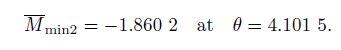
In the second case, a negative torque M is applied on the structural configuration at the rotating angle θ = θ'max, and the value of M decreases from 0 to -4. As shown in Fig. 4(c), the structural configuration changes continuously as the magnitude of the torque increases to |Mmin2|, at which all side strings remain in touch with each other. A further increase in the magnitude of the torque beyond|Mmin2|causes the structure to jump from the state where θ = 4.101 5 to the state where
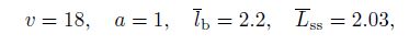
Structure-2 is an 18-prismatic tensegrity with the parameters as follows:

|
| Fig. 5 Normalized torque M = M/(gssr2) versus rotating angle θ for prismatic tensegrity Structure-2 subjected to loading via imposed rotating angle, applied torque starting at θ = 0, and applied torque starting at θ = θ'max |
First, a torque M increasing from 0 to 1 is applied on the structural configuration where θ = 0. The mechanical response of the structure is shown in Fig. 5(b), which is similar to that of Structure-1. Before M reaches Mmax, the structure deforms continuously. Once the torque exceeds Mmax, however, the structural configuration jumps from θ = 0.918 0 to θ = θ'max = 4.886 9, indicating the snapping instability. The side strings and bars intersect each other in the configuration that results from the instability.
Next, a negative torque M from 0 to -1 is applied on the structural configuration at θ = θ'max. As shown in Fig. 5(c), the structure deforms continuously until M reaches Mmin1. The side strings remain in touch with each other in the value range 0≤M≤Mmin2, and become detached past this point until Mmin1, which is different from the behavior of Structure-1. Once the magnitude of the torque exceeds|Mmin1|, the structure jumps from θ = 4.241 2 to θ = θmin = -1.396 3, corresponding to the other snapping instability.
4.3 RemarksThe above investigations clearly show that snapping instability exists in the deformation responses of the prismatic tensegrities subject to the torque loadings about the prismatic axis. Each prismatic tensegrity can exhibit two types of structural instability. One type starts from the self-equilibrated state where θ = 0, and the other starts from the self-equilibrated state where θ = θ'max. In the former case, the instability of all the prismatic tensegrities is similar, which happens once the torque exceeds a critical value in the deformation range 0 < θ < π. In the latter case, however, some structures (e.g., Structure-1) undergo instability when the side strings intersect each other, while others (e.g., Structure-2) show instability after the side strings become separated. The self-stress level in the structure has no effect on the existence of the snapping instability, but can affect the critical state of instability.
At a critical state of the snapping instability, a small change of the torque produces a large change in the rotating angle of the structure. A prismatic tensegrity shows two self-equilibrated and stable states with different heights (e.g., the ratio of the two heights is 0.58 in Structure-2). Therefore, these structures hold potential applications in sensitive sensors, deformation amplifiers, advanced actuators, and protective and folding/unfolding devices.
5 Experimental validationWe also performed an experiment to validate the snapping instability behavior of the pris-matic tensegrities. A 3-prismatic tensegrity is shown in Fig. 6. The side strings are made of rubber ropes with the natural length of 120mm, the bars are made of stainless steel tubes with 200mm in the length and 6mm in the outer diameter, and the end plates are made of engineer-ing plastic with the diameter of 150mm and the thickness of 5mm. In each end plate, we made three pairs of through-holes, locating on a circle of 130mm in the diameter (see Fig. 6(a)). The side strings pass through the holes to connect the bars according to the structural topology defined in Fig. 2.

|
| Fig. 6 Schematic of flow configuration |
The 3-prismatic tensegrity has two self-equilibrated and stable states, i.e., State-I and State-II (see Fig. 6). In State-I, there is no interference of elements (see Fig. 6(a)), while in State-II, all bars and side strings intersect each other at the center of the structure, and each side string kinks from an original straight line into two non-collinear segments (see Fig. 6(c)). The two states are consistent with the theoretical prediction (see Figs. 3(b) and 3(f)).
The structure deforms gradually when a small torque is applied on State-I. It always returns to Configuration-I upon the removal of the load, indicating the stability of the current state. However, as soon as the applied torque exceeds Mmax, the structure is seen to jump to State-II, consistent with the predicted snapping instability. In this case, the structure will remain in Configuration-II even when the torsional load is fully released. Similarly, applying a sufficiently large torque in the reverse direction leads to the reverse snapping from Configuration-II to Configuration-I. Figure 6(b) shows an intermediate state during the transformation from State-II to State-I, which is consistent with the theoretical prediction given in Fig. 3(e).
6 ConclusionsIn this paper, we have investigated the snapping instability associated with the prismatic tensegrities with the top and bottom surfaces subjected to torque loadings about the prismatic axis. Such structures have two self-equilibrated stable states and one self-equilibrated but un-stable state. Under sufficiently large torques about the prismatic axis, the prismatic tensegrity exhibits snapping instability between their two self-equilibrated stable states. The instability behavior has been experimentally validated by a 3-prismatic tensegrity. The structures with the snapping instability properties may find applications in the fields such as advanced sensors and actuators, energy storage/adsorption structures, and folding/unfolding devices.
| [1] | Skelton, R. E. and de Oliveira, M. C. Tensegrity Systems, Springer, Dordrecht (2009) |
| [2] | Sultan, C. Tensegrity: 60 years of art, science, and engineering. Advances in Applied Mechanics, 43, 69-145 (2009) |
| [3] | Rhode-Barbarigos, L., Ali, N. B. H., Motro, R., and Smith, I. F. C. Designing tensegrity modules for pedestrian bridges. Engineering Structures, 32, 1158-1167 (2010) |
| [4] | Sunny, M. R., Sultan, C., and Kapania, R. K. Optimal energy harvesting from a membrane attached to a tensegrity structure. AIAA Journal, 52, 307-319 (2014) |
| [5] | Fraternali, F., Senatore, L., and Daraio, C. Solitary waves on tensegrity lattices. Journal of the Mechanics and Physics of Solids, 60, 1137-1144 (2012) |
| [6] | Stamenović, D. and Ingber, D. E. Tensegrity-guided self assembly: from molecules to living cells. Soft Matter, 5, 1137-1145 (2009) |
| [7] | Veenendaal, D. and Block, P. An overview and comparison of structural form finding methods for general networks. International Journal of Solids and Structures, 49, 3741-3753 (2012) |
| [8] | Zhang, L. Y., Li, Y., Cao, Y. P., Feng, X. Q., and Gao, H. J. Self-equilibrium and super-stability of truncated regular polyhedral tensegrity structures: a unified analytical solution. Proceedings of the Royal Society, A: Mathematical Physical and Engineering Sciences, 468, 3323-3347 (2012) |
| [9] | Koohestani, K. and Guest, S. D. A new approach to the analytical and numerical form-finding of tensegrity structures. International Journal of Solids and Structures, 50, 2995-3007 (2013) |
| [10] | Feng, X. Q., Li, Y., Cao, Y. P., Yu, S. W., and Gu, Y. T. Design methods of rhombic tensegrity structures. Acta Mechanica Sinica, 26, 559-565 (2010) |
| [11] | Li, Y., Feng, X. Q., Cao, Y. P., and Gao, H. J. Constructing tensegrity structures from one- bar elementary cells. Proceedings of the Royal Society, A: Mathematical Physical and Engineering Sciences, 466, 45-61 (2010) |
| [12] | Zhang, L. Y., Zhao, H. P., and Feng, X. Q. Constructing large-scale tensegrity structures with bar-bar connection using prismatic elementary cells. Archive of Applied Mechanics, 85, 383-394 (2015) |
| [13] | Defossez, M. Shape memory effect in tensegrity structures. Mechanics Research Communications, 30, 311-316 (2003) |
| [14] | Li, Y., Feng, X. Q., Cao, Y. P., and Gao, H. J. A Monte Carlo form-finding method for large scale regular and irregular tensegrity structures. International Journal of Solids and Structures, 47, 1888-1898 (2010) |
| [15] | Xu, X. and Luo, Y. Z. Multistable tensegrity structures. Journal of Structural Engineering-ASCE, 137, 117-123 (2011) |
| [16] | Micheletti, A. Bistable regimes in an elastic tensegrity system. Proceedings of the Royal Society, A: Mathematical Physical and Engineering Sciences, 469, 20130052 (2013) |
| [17] | Zhang, L. Y., Li, Y., Cao, Y. P., and Feng, X. Q. Stiffness matrix based form-finding method of tensegrity structures. Engineering Structures, 58, 36-48 (2014) |
| [18] | Guest, S. D. The stiffness of tensegrity structures. IMA Journal of Applied Mathematics, 76, 57-66 (2011) |
| [19] | Fraternali, F., Carpentieri, G., and Amendola, A. On the mechanical modeling of the extreme softening/stiffening response of axially loaded tensegrity prisms. Journal of the Mechanics and Physics of Solids, 74, 136-157 (2015) |
| [20] | Moored, K. W. and Bart-Smith, H. Investigation of clustered actuation in tensegrity structures. International Journal of Solids and Structures, 46, 3272-3281 (2009) |
| [21] | Ali, N. B. H., Rhode-Barbarigos, L., and Smith, I. F. C. Analysis of clustered tensegrity structures using a modified dynamic relaxation algorithm. International Journal of Solids and Structures, 48, 637-647 (2011) |
| [22] | Zhang, L., Lu, M. K., Zhang, H. W., and Yan, B. Geometrically non-linear elasto-plastic analysis of clustered tensegrity based on the co-rotational approach. International Journal of Mechanical Sciences, 93, 154-165 (2015) |
| [23] | Zhang, L., Gao, Q., Liu, Y., and Zhang, H.W. An efficient finite element formulation for non-linear analysis of clustered tensegrity. Engineering Computations, 33 (2016) DOI 10.1108/EC-08-2014- 0168 |
| [24] | Kebiche, K., Kazi-Aoual, M. N., and Motro, R. Geometrical non-linear analysis of tensegrity systems. Engineering Structures, 21, 864-876 (1999) |
| [25] | Tran, H. C. and Lee, J. Geometric and material non-linear analysis of tensegrity structures. Acta Mechanica Sinica, 27, 938-949 (2011) |
| [26] | Zhang, L., Gao, Q., and Zhang, H. W. An efficient algorithm for mechanical analysis of bimodular truss and tensegrity structures. International Journal of Mechanical Sciences, 70, 57-68 (2013) |
| [27] | Zhang, L. Y., Li, Y., Cao, Y. P., Feng, X. Q., and Gao, H. J. A numerical method for simulating non-linear mechanical responses of tensegrity structures under large deformations. Journal of Applied Mechanics-Transactions of the ASME, 80, 061018 (2013) |
| [28] | Stamenović, D., Fredberg, J. J., Wang, N., Butler, J. P., and Ingber, D. E. A microstructural approach to cytoskeletal mechanics based on tensegrity. Journal of Theoretical Biology, 181, 125- 136 (1996) |
| [29] | Oppenheim, I. J. and Williams, W. O. Geometric effects in an elastic tensegrity structure. Journal of Elasticity, 59, 51-65 (2000) |
| [30] | Crane, C. D., Duffy, J., and Correa, J. C. Static analysis of tensegrity structures. Journal of Mechanical Design, 127, 257-268 (2005) |
| [31] | Plaut, R. H. and Virgin, L. N. Vibration and snap-through of bent elastica strips subjected to end rotations. Journal of Applied Mechanics-Transactions of the ASME, 76, 041011 (2009) |
| [32] | Fargette, A., Neukirch, S., and Antkowiak, A. Elastocapillary snapping: capillarity induces snap- through instabilities in small elastic beams. Physical Review Letters, 112, 137802 (2014) |
| [33] | Mao, G. Y., Li, T. F., Zou, Z. N., Qu, S. X., and Shi, M. X. Prestretch effect on snap-through instability of short-length tubular elastomeric balloons under inflation. International Journal of Solids and Structures, 51, 2109-2115 (2014) |
| [34] | Shekastehband, B., Abedi, K., Dianat, N., and Chenaghlou, M. R. Experimental and numerical studies on the collapse behavior of tensegrity systems considering cable rupture and strut collapse with snap-through. International Journal of Non-Linear Mechanics, 47, 751-768 (2012) |
| [35] | Li, T. F., Keplinger, C., Baumgartner, R., Bauer, S., Yang, W., and Suo, Z. G. Giant voltage- induced deformation in dielectric elastomers near the verge of snap-through instability. Journal of the Mechanics and Physics of Solids, 61, 611-628 (2013) |
| [36] | Dai, F. H., Li, H., and Du, S. Y. Cured shape and snap-through of bistable twisting hybrid[0/90/metal]T laminates. Composites Science and Technology, 86, 76-81 (2013) |
| [37] | Avramov, K. V. and Mikhlin, Y. V. Snap-through truss as an absorber of forced oscillations. Journal of Sound and Vibration, 290, 705-722 (2006) |
| [38] | Connelly, R. and Terrell, M. Globally rigid symmetric tensegrities. Structural Topology, 21, 59-79 (1995) |