 2016, Vol. 37
Article Information
- Junsheng DUAN, Zongxue LI, Jinyuan LIU. 2016.
- Pull-in instability analyses for NEMS actuators with quartic shape approximation
- Appl. Math. Mech. -Engl. Ed., 37(3): 303-314
- http://dx.doi.org/10.1007/s10483-015-2007-6
Article History
- Received Jan. 9, 2015;
- in final form Apr. 18, 2015


2. College of Computer and Information, Inner Mongolia Medical University, Hohhot 010110, China;
3. Department of Information Management, Party School of the Inner Mongolia Committee of the Communist Party of China, Hohhot 010070, China
Beam-type electrostatic actuators are common components for the construction of micro-electromechanical systems (MEMSs) and nano-electromechanical systems (NEMSs)[1]. A can-tilever MEMS/NEMS actuator is composed of a cantilever beam of the length L with a uniform rectangular cross section of the width w and the thickness h, which is suspended over a con-ductive substrate and separated by a dielectric spacer (see Fig. 1).

|
| Fig. 1 Schematic representation of cantilever actuator: I cantilever beam; II dielectric spacer; III fixed ground electrode |
A voltage difference between the two electrodes causes the upper movable electrode to de-flect towards the fixed ground electrode. At a critical voltage, the movable electrode becomes unstable, and collapses onto the ground electrode. The voltage and deflection of the actuator at this critical state are used to designate the pull-in parameters[2].
The pull-in behavior and parametric analyses of MEMS/NEMS actuators have been widely studied by many authors[2, 3, 4, 5, 6, 7, 8, 9, 10, 11, 12, 13, 14, 15, 16, 17, 18]. For NEMS actuators, the effects of the intermolecular forces[19, 20, 21, 22] such as the van der Waals force and the Casimir force are always considered.
The distributed parameter model of the deflection of nano-beams constitutes a boundary value problem for a non-linear fourth-order ordinary differential equation. Lin and Zhao[16] and Guo and Zhao[23] studied the dynamic behavior of nano-scale electrostatic actuators by consid-ering the effect of the van der Waals force. Guo and Zhao[24] and Lin and Zhao[25] investigated the influence of the van derWaals force and the Casimir force on the stability of the electrostatic torsional NEMS actuators. Abadyan et al.[9], Koochi et al.[5, 13], Noghrehabadi et al.[14], and Duan et al.[26] used the Adomian decomposition method to treat similar models of non-linear boundary value problems. Ma et al.[17] studied the instability of cantilever NEMS actuators by the homotopy perturbation method. Ramezani et al.[6, 15] and Duan and Rach[18] investigated the instability of nano-cantilevers with the assumption of a second-degree polynomial as the shape function of the beam during the deflection.
Surface energy effects are very important in modeling a nano-scale structure due to the large surface area/volume ratio of the structure. Surface effects play a crucial role in the pull-in performance of nano-actuators. Gurtin and Murdoch[27] developed a continuum theory to model both the residual surface stress and the surface elasticity to investigate the surface effects on the elastic behavior of beam-type nano-structures[28, 29, 30], where the Casimir attraction and fringing field effects were neglected.
In this paper, we consider the distributed parameter model of the NEMS cantilever actuators, incorporating the effects of the surface energy, the Casimir force, and the fringing field, and investigate the pull-in parameters. A new shape function is used for the beam during the deflection. In Section 2, we establish the model as a boundary value problem for a non-linear fourth-order ordinary differential equation. Our main results are presented in Section 3, where a quartic shape function of the beam during the deflection is proposed, satisfying all of the four boundary values. The Gaussian quadrature rule is used to treat the involved integrations, retaining the designed parameters in the evaluated formulas. Section 4 summarizes our conclusions.
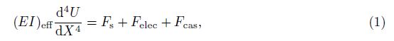
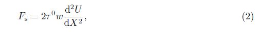
2 Distributed parameter modelThe governing equation for the distributed parameter model based on the Euler-Bernoulli beam assumptions can be written as follows[5, 6]:
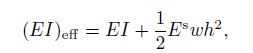
Based on the composite beam theory and the assumption that the thickness of the surface layer is much smaller than the beam thickness h, the effective bending rigidity (EI)eff for a beam with a rectangular cross section can be derived as follows:
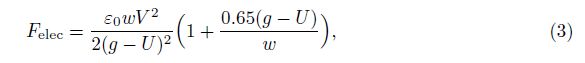

Substituting Eqs. (2), (3), and (4) into Eq. (1) and introducing the dimensionless variables u = U/g and x = X/L, we can transform the governing equation into the dimensionless form as follows:

For the cantilever NEMS, the boundary conditions are

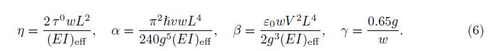
We denote the maximum cantilever tip deflection as utip = u(1), and investigate the pull-in parameters utipPI and βPI. From the third equality in Eq. (6), the pull-in voltage V PI can be characterized in terms of the pull-in parameter βPI as follows:
First, we convert Eqs. (5)-(7) into an equivalent non-linear integral equation[35] so as to determine all of the integration constants in terms of the boundary conditions. Secondly, we rewrite Eq. (5) in its operator form as follows:

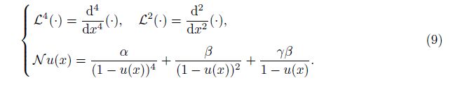
Introducing the definite integral operators L0-2(·) and L1-2(·) as follows:


To analyze the deflection and pull-in parameters of the cantilever beam, some authors pro-posed the following second-degree function to approximate the beam deflection[6, 15, 18, 36, 37]:

Here, we present a new approximation of the beam by the quartic function
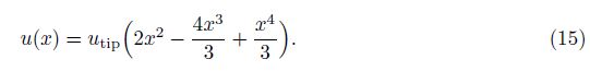
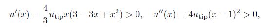
Substituting u(x) = 0 into the right-hand side of Eq. (12), we can obtain the approximation of the beam as follows:

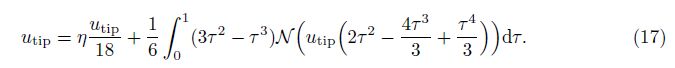
The integral on the right-hand side of Eq. (17) cannot be analytically calculated by the available computer algebra systems that utilize the Risch algorithm such as MATHEMATICA. We mention that this integral can be exactly and analytically calculated if the second-degree shape function (14) is used. Here, we rely on a numeric integral method. To acquire the superior accuracy of a numeric integral by use of the minor integral nodes, we use the Gaussian quadrature rule. For the relevant details of the Gaussian quadrature rule, see Appendix A[38].
To perform the integration in Eq. (17) by the Gaussian quadrature rule, we use the trans-formation τ = (z + 1)/2 to obtain the canonical form as follows:


From Eq. (19) and substituting the operator N into Eq. (9), we can obtain
For example, we take n = 5 and solve for β from Eq. (19). Then, we have
We take α = 0.4, γ = 0.6, and η = 0 and 2, respectively, and plot the curves of β versus utip in Fig. 2.

|
| Fig. 2 Curves of β versus utip for α = 0.4, γ = 0.6, and η = 0, 2 |
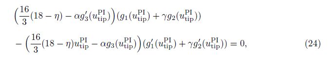
The pull-in parameters utipPI and βPI are determined by
Equation (22) determines the pull-in parameter utipPI . We next replace utip by utipPI and rewrite Eq. (22) as follows:

From Eq. (23), we can analyze the effects of α, γ , and η on utipPI. From Eq. (25), we can consider the relation between βPI and α, γ, or η.
To achieve higher accuracy, we take ten integral nodes, i.e., n = 10, to apply the Gaussian quadrature rule on Eq. (19) in the sequel. We remark that increasing the number of the integral nodes does not cause any technical difficulty, but only adds some additional calculation work.
For the specified values of α = 0.2 and γ = 0.65, α = 0.45 and γ = 0.65, and α = 0.7 and γ = 0.65, we plot the curves of utipPI and βPI versus η by use of Eqs. (23) and (25) (see Fig. 3). It is shown that utipPI decreases monotonically and βPI decreases when η increases. Moreover, utipPI and βPI decrease when α increases, which is consistent with the results in Refs. [5] and [6].

|
| Fig. 3 Curves of utipPI and βPI versus η for γ = 0.65 and various α |
Through Eqs. (23) and (25), we can obtain the numeric values of utipPI and βPI for different η. The obtained results are listed in Tables 1-3. From the tables, we can see that βPI decreases non-linearly as η increases, which means that the curves in Fig. 3(b) are not straight, but are slightly concave.


Next, we consider two typical special cases.
Case 1 Electrostatic microactuators
Neglecting the intermolecular forces, i.e., setting α = 0, leads to the cantilever actuator model in the MEMS. In this case, from Eqs. (20) and (24), we can obtain the equations as follows:

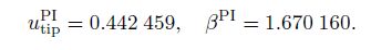
Especially, if we neglect the influence of the fringing field and the surface effect, i.e., setting γ = 0 and η = 0, we can obtain the pull-in parameters as follows:
Case 2 Freestanding nano-actuators
When the nano-actuator becomes freestanding, the voltage difference V between the can-tilever beam and the substrate shown in Fig. 1 vanishes. Therefore, the electrostatic force parameter satisfies β = 0. In this case, from Eq. (20), we have
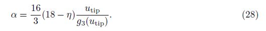
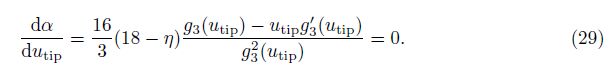
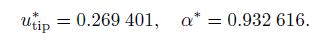
In Fig. 4, we plot the curve of α versus utip for η = 0. The critical values of α and utip are determined by

|
| Fig. 4 Curve of α versus utip for η = 0 |
No solution exists when α is greater than the critical value α*, since the cantilever beam collapses onto the substrate. Therefore, the critical value α* is considered to be crucial in the cantilever design.
From the second formula in Eq. (6), we can write α ∝ L4/g5, where L is the length of the cantilever beam, and g is the gap between the two electrodes. The maximum length of the cantilever beam, which does not collapse onto the substrate due to the intermolecular forces, is called the detachment length[16]. It is a basic design parameter for NEMSs. If the length of the beam is fixed, one can calculate the minimum gap gmin between the beam and the substrate to ensure that the beam does not adhere to the substrate due to the intermolecular forces. The detachment length and the minimum gap of the cantilever beam can be obtained from the critical value α* and the second formula in Eq. (6).
Finally, we indicate that the calculation is readily amenable to the increase in the number of the integral nodes in the Gaussian quadrature rule, although the present results for 10 integral nodes are sufficiently accurate. We have checked that the results for 20 integral nodes are almost identical with the present results for 10 integral nodes. When α = 0.7, γ = 0.65, and η = 3, the difference between the obtained utipPI for 10 nodes and 20 nodes is less than 1.117 77× 10-12.
4 ConclusionsWe have considered the distributed parameter model of the NEMS cantilever actuators incorporating the effects of the surface energy, the Casimir force, and the fringing field. A quartic polynomial is proposed as the shape function for the cantilever beam, and the analytic expressions for the tip deflection and pull-in parameters of the beam are derived by using the Gaussian quadrature rule. The new quartic shape function satisfies all of the four boundary values, but the quadratic shape function used in the previous investigations satisfies only three of the four boundary values. Although we have applied a numeric integral method, we derive the analytic expressions preserving the model parameters for the tip deflection and pull-in parameters of the beam. The MEMS cantilever actuators and the freestanding nano-actuators are included as two special cases in our parametric analyses. The results show that our analyses for the influence of the surface energy, the Casimir force, and the fringing field on the pull-in instability are convenient.
| [1] | Pelesko, J. A. and Bernstein, D. H. Modeling MEMS and NEMS, Chapman and Hall/CRC, Boca Raton (2003) |
| [2] | Zhang, W. M., Yan, H., Peng, Z. K., and Meng, G. Electrostatic pull-in instability in MEMS/NEMS: a review. Sensors and Actuators, A: Physical, 214, 187-218 (2014) |
| [3] | Kuang, J. H. and Chen, C. J. Adomian decomposition method used for solving non-linear pull-in behavior in electrostatic micro-actuators. Mathematical and Computer Modelling, 41, 1479-1491 (2005) |
| [4] | Lin, W. H. and Zhao, Y. P. Pull-in instability of micro-switch actuators: model review. Interna- tional Journal of Nonlinear Sciences and Numerical Simulation, 9, 175-183 (2008) |
| [5] | Koochi, A., Kazemi, A. S., Beni, Y. T., Yekrangi, A., and Abadyan, M. Theoretical study of the effect of Casimir attraction on the pull-in behavior of beam-type NEMS using modified Adomian method. Physica E: Low-dimensional Systems and Nanostructures, 43, 625-632 (2010) |
| [6] | Ramezani, A., Alasty, A., and Akbari, J. Closed-form solutions of the pull-in instability in nano- cantilevers under electrostatic and intermolecular surface forces. International Journal of Solids and Structures, 44, 4925-4941 (2007) |
| [7] | Lin, W. H. and Zhao, Y. P. Non-linear behavior for nano-scale electrostatic actuators with Casimir force. Chaos, Solitons and Fractals, 23, 1777-1785 (2005) |
| [8] | Koochi, A. and Abadyan, M. Efficiency of modified Adomian decomposition for simulating the instability of nano-electromechanical switches: comparison with the conventional decomposition method. Trends in Applied Sciences Research, 7, 57-67 (2012) |
| [9] | Abadyan, M. R., Beni, Y. T., and Noghrehabadi, A. Investigation of elastic boundary condition on the pull-in instability of beam-type NEMS under van der Waals attraction. Procedia Engineering, 10, 1724-1729 (2011) |
| [10] | Soroush, R., Koochi, A., Kazemi, A. S., Noghrehabadi, A., Haddadpour, H., and Abadyan, M. Investigating the effect of Casimir and van der Waals attractions on the electrostatic pull-in instability of nano-actuators. Physica Scripta, 82, 045801 (2010) |
| [11] | Salekdeh, A. Y., Koochi, A., Beni, Y. T., and Abadyan, M. Modeling effects of three nano-scale physical phenomena on instability voltage of multi-layer MEMS/NEMS: material size dependency, van der Waals force and non-classic support conditions. Trends in Applied Sciences Research, 7, 1-17 (2012) |
| [12] | Beni, Y. T., Koochi, A., and Abadyan, M. Theoretical study of the effect of Casimir force, elastic boundary conditions and size dependency on the pull-in instability of beam-type NEMS. Physica E: Low-dimensional Systems and Nanostructures, 43, 979-988 (2011) |
| [13] | Koochi, A., Kazemi, A., Khandani, F., and Abadyan, M. Influence of surface effects on size- dependent instability of nano-actuators in the presence of quantum vacuum fluctuations. Physica Scripta, 85, 035804 (2012) |
| [14] | Noghrehabadi, A., Ghalambaz, M., and Ghanbarzadeh, A. A new approach to the electrostatic pull-in instability of nano-cantilever actuators using the ADM-Padé technique. Computers and Mathematics with Applications, 64, 2806-2815 (2012) |
| [15] | Ramezani, A., Alasty, A., and Akbari, J. Closed-form approximation and numerical validation of the influence of van der Waals force on electrostatic cantilevers at nano-scale separations. Nanotechnology, 19, 015501 (2008) |
| [16] | Lin, W. H. and Zhao, Y. P. Dynamic behavior of nano-scale electrostatic actuators. Chinese Physics Letters, 20, 2070-2073 (2003) |
| [17] | Ma, J. B., Jiang, L., and Asokanthan, S. F. Influence of surface effects on the pull-in instability of NEMS electrostatic switches. Nanotechnology, 21, 505708 (2010) |
| [18] | Duan, J. S. and Rach, R. A pull-in parameter analysis for the cantilever NEMS actuator model including surface energy, fringing field and Casimir effects. International Journal of Solids and Structures, 50, 3511-3518 (2013) |
| [19] | Israelachvili, J. N. Intermolecular and Surface Forces, Academic Press, London (1992) |
| [20] | Mostepanenko, V. M. and Trunov, N. N. The Casimir Effect and Its Application, Oxford Science Publications, New York (1997) |
| [21] | Lamoreaux, S. K. The Casimir force: background, experiments, and applications. Reports on Progress in Physics, 68, 201-236 (2005) |
| [22] | Rodriguez, A. W., Capasso, F., and Johnson, S. G. The Casimir effect in microstructured geome- tries. Nature Photonics, 5, 211-221 (2011) |
| [23] | Guo, J. G. and Zhao, Y. P. Dynamic stability of electrostatic torsional actuators with van der Waals effect. International Journal of Solids and Structures, 43, 675-685 (2006) |
| [24] | Guo, J. G. and Zhao, Y. P. Influence of van der Waals and Casimir forces on electrostatic torsional actuators. Journal of Microelectromechanical Systems, 13, 1027-1035 (2004) |
| [25] | Lin, W. H. and Zhao, Y. P. Stability and bifurcation behaviour of electrostatic torsional NEMS varactor influenced by dispersion forces. Journal of Physics, D: Applied Physics, 40, 1649-1654 (2007) |
| [26] | Duan, J. S., Rach, R., and Wazwaz, A. M. Solution of the model of beam-type micro-and nano- scale electrostatic actuators by a new modified Adomian decomposition method for non-linear boundary value problems. International Journal of Non-Linear Mechanics, 49, 159-169 (2013) |
| [27] | Gurtin, M. E. and Murdoch, A. I. A continuum theory of elastic material surfaces. Archive for Rational Mechanics and Analysis, 57, 291-323 (1975) |
| [28] | He, J. and Lilley, C. M. Surface effect on the elastic behavior of static bending nano-wires. Nano Letters, 8, 1798-1802 (2008) |
| [29] | Wang, G. F. and Feng, X. Q. Surface effects on buckling of nano-wires under uniaxial compression. Applied Physics Letters, 94, 141913 (2009) |
| [30] | Fu, Y. and Zhang, J. Size-dependent pull-in phenomena in electrically actuated nano-beams in- corporating surface energies. Applied Mathematical Modelling, 35, 941-951 (2011) |
| [31] | Miller, R. E. and Shenoy, V. B. Size-dependent elastic properties of nano-sized structural elements. Nanotechnology, 11, 139-147 (2000) |
| [32] | Jiang, L. Y. and Yan, Z. Timoshenko beam model for static bending of nano-wires with surface effects. Physica E: Low-dimensional Systems and Nanostructures, 42, 2274-2279 (2010) |
| [33] | Gupta, R. K. Electrostatic Pull-in Test Structure Design for In-situ Mechanical Property Measure- ments of Microelectromechanical Systems (MEMS), Ph.D. dissertation, Massachusetts Institute of Technology, Cambridge (1997) |
| [34] | Huang, J. M., Liew, K. M., Wong, C. H., Rajendran, S., Tan, M. J., and Liu, A. Q. Mechanical design and optimization of capacitive micromachined switch. Sensors Actuators, A: Physical, 93, 273-285 (2001) |
| [35] | Duan, J. S. and Rach, R. A new modification of the Adomian decomposition method for solving boundary value problems for higher order non-linear differential equations. Applied Mathematics and Computation, 218, 4090-4118 (2011) |