 2016, Vol. 37
Shanghai University
Article Information
- Xiao YANG, Jin HUANG, Yu OUYANG. 2016.
- Bending of Timoshenko beam with effect of crack gap based on equivalent spring model
- Appl. Math. Mech. -Engl. Ed., 37(4): 513-528
- http://dx.doi.org/10.1007/s10483-016-2042-9
Article History
- Received Apr. 2, 2015;
- in final form Revised Jul. 27, 2015


Various cracks can easily appear in reinforced concrete beam,and in fact,the reinforced concrete beam with harmless cracks is in service state frequently. However,initiations and propagations of certain type of crack in the reinforced concrete beam may make the beam’s flexibility increase dramatically and render the reinforced concrete beam out of use due to its large deflection. Meanwhile,there also exist harmless cracks in the reinforced concrete beam, which have little influence on the bearing capacity of reinforced concrete beam. Therefore,it is important for the performance analysis and the rehabilitation design of the reinforced concrete beam with cracks. Nowadays,damage detection[1, 2, 3] of the cracks in the beam and the analysis of the static/dynamic performances[4, 5, 6, 7, 8] of the cracked beam have attracted much attention of the researchers and engineers in civil engineering and mechanical engineering fields,and a lot of research achievements have been made in the last decades.
The discrete spring model of the crack,which neglects the initiation and propagation of the crack,is usually used in the analysis of the global mechanical performance of the cracked beam,in which the crack in the beam is equivalent to a linear or nonlinear internal rotational spring. At present,the linear open crack model,in which it is assumed that the crack is always open,and the rigidity of the rotational spring is independent of the couple,has been applied extensively in studying the static deformation[6, 9, 10, 11],stability analysis[12, 13, 14],and dynamic characteristics[3, 14, 15, 16] of the cracked beam. However,the open crack model can only be used in the U-type or V-type crack with the relative large crack gap,in which it is assumed that the crack cannot be closed during the deformation. Nevertheless,for the U-type or V-type crack with relative small crack gap,or for the capillary crack,the crack can easily be closed during the beam deformation. In such a case,the open crack model is no longer applicable, and the breathing crack model or the switching crack model should be used. For the breathing crack model[7, 8, 17, 18],it is assumed that the transition between the open and closed states of the crack is a smooth process. For the switching crack model[6, 19, 20],it is assumed that the crack has only two states (the open state and the closed state),and the crack state transition is abrupt. Although the breathing crack model provides the abundant information on the crack, it is difficult to determine the constitutive relation between its rigidity and the crack state. Furthermore,the final state of the crack and the ultimate capacity of the beam are related only to the open or closed state of the crack. Therefore,the switching crack model,which not only considers the open and closed states of the crack but also has the advantage of being simpler mathematical treatment and easier physical parametric measurement,has been adopted extensively in the performance analysis of cracked beam.The classical analytical approach for analyzing the bending deformation of the cracked beam with the discrete spring model is based on the partition of the cracked beam into several sub-beams between two consecutive cracks. Then,the general bending of the sub-beam is analyzed,and the bending of the global cracked beam can be obtained by imposing the boundary conditions and the pertinent continuity conditions of the rotational spring between two adjacent sub-beams. With this approach,Challamel and Xiang[6] investigated the stability of the cracked column with one or two cracks,and the influence of the crack closure on the critical load of the cracked column was examined. Bakhtiari-Nejad et al.[21] studied the dynamical characteristics of the beam with two cracks,and Khaji et al.[10] dealt with the dynamical characteristics of the Timoshenko beam with one crack. However,the numbers of the continuity conditions at the crack locations increase rapidly with the crack number. The solution approach becomes tedious,and the computation effort increases. It is difficult to get a simple explicit solution. A completely different strategy is to make use of the so-called Dirac delta function to handle the discontinuities along the beam and to obtain the simpler explicit solution. Buda and Caddemi[9] and Caddemi and Cali´o[12, 15, 16, 22] introduced the minus Dirac delta function to describe the rigidity damage at the crack of the beam,but this description resulted in a negative rigidity of the beam which is impossible in reality. Therefore,this strategy is imperfect in physics. To deal with this imperfection,Palmeri and Cicirello[5] and Cicirello and Palmeri[19] used the positive Dirac delta function to describe the bending flexibility,which avoids the physical imperfection completely.At present,for the switching crack model,the open or closed state of the crack is determined by the positive or negative value of the bending curvature[20, 23] or of the axial strain[19, 24] at the crack location of the beam,and the effect of the crack gap has not been taken into consideration. In this study,the effect of the crack gap on the bending deformation of the cracked beam is investigated with the switching crack model. At first,considering the effect of the crack gap, the equivalent flexural rigidity is derived physically for the beam with the unilateral switching crack by the Dirac delta function. Then,a general closed-form solution for the bending of the Timoshenko beam with an arbitrary number of unilateral switching cracks was derived, and a general computational strategy for determining the undermined constants was presented. Based on the closed-form solution,three examples of the cracked beam bending are explored, and the influence of the beam’s slenderness ratio and the crack’s depth on the crack state andbending performance of the Timoshenko beam is discussed. It is shown from the numerical results that there exists a cusp on the deflection curve and a jump on the rotation angle curve at a crack location due to the existence of crack,and the deflection-load curve of the cracked beam is bilinear. Furthermore,for the open crack,the flexibility of the cracked beam decreases with the increase of the beam’s slenderness ratio and the decrease of the crack depth.
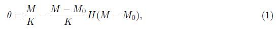
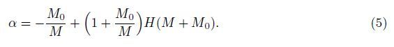
2 Equivalent flexural rigidity of beam with switching crack modelFirst,the constitutive relation of the unidirectional rotational spring is discussed. As shown in Fig. 1,consider a linkage mechanism composed of two rigid straight rods connected by a unidirectional rotational spring. It is assumed that,when the linkage is subjected to a counterclockwise couple M,the linkage mechanism can undergo an arbitrary rotation angle θ = M/K in the counter-clockwise direction with the rigidity K. However,for the clockwise couple M, its rigidity is still K when the couple M<M0,but when the couple M ≥ M0,the rotation angle θ0 = M0/K of the rotational spring is independent of the couple M and keeps constant. Therefore,the constitutive relation of the linkage mechanism (the unidirectional rotational spring) can be expressed as

|
| Fig. 1 Deformation of unilateral rotational spring and its constitutive relation |
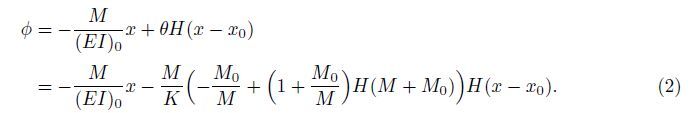
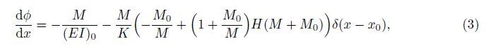
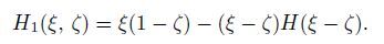
Suppose that there exists an open crack on the bottom surface of a beam at the location x = x0 (see Fig. 2(a)),and it is assumed that the bending rigidity of the perfect beam is (EI)0. Now,the effect of the crack with gap is equivalent to a nonlinear unidirectional rotational spring[18, 24] satisfying the constitutive relation (1). It is assumed that the crack is closed after the rotation angle θ reaches θ0 = M0/K,where M0 is the critical bending moment for crack closure. When M >M0,the crack disappears,and the cracked beam becomes a perfect beam. In accordance with the sign standard of the beam bending model,when the cracked beam is subjected to a couple M at its end,the rotation angle φ of the beam’s cross section can be expressed as

|
| Fig. 2 Timoshenko beam with switching crack |
Denote the equivalent flexural rigidity of the beam with a unilateral switching crack on the bottom surface of the beam by (EI)e. Then,from the formula
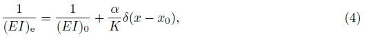
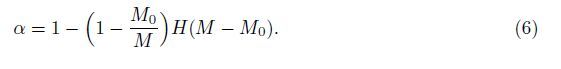
Similarly,for the beam with a unilateral switching crack on the top surface of the beam (see Fig. 2(b)),the equivalent flexural rigidity (EI)e can also be expressed as (4),but the parameter α takes the form of
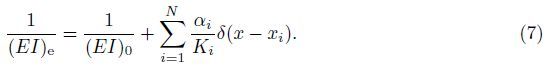
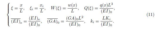
Suppose that there exist N unilateral switching cracks on a Timoshenko beam with the flexural rigidity (EI)0,the shear rigidity (GA)0,and the length L subjected to a transversal load q(x). Denote the equivalent rigidity of the crack i at the location x = xi by Ki (i = 1,2,· · · ,N). Then,the equivalent flexural rigidity (EI)e can be expressed as
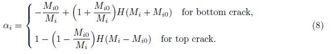
If the bending moment of the beam at the crack i is Mi,and the corresponding critical bending moment for the crack closure is Mij,then it has
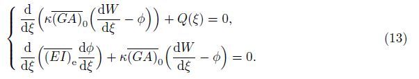
Neglecting the effect of the crack on the shear deformation and denoting the deflection and the rotation angle of the cross section of the cracked Timoshenko beam by w(x) and φ(x), respectively,the governing equations are as follows[25]:
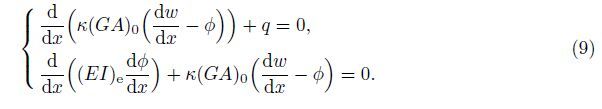
The bending moment M(x) and the shear force Fs(x) on the beam’s cross section are
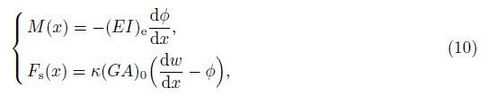
Introduce the following dimensionless variables and parameters:
Denote mi = MiL/(EI)0 and mi0 = Mi0L/(EI)0 = kiθi0. The expression (8) is still valid in the dimensionless sense if Mi and Mi0 are replaced by mi and mi0,respectively.
The dimensionless governing equations of the cracked Timoshenko beam are
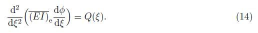
From the governing equations (13),it is easy to obtain
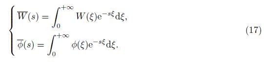
Denote the Laplace transform of the functions W(ξ) and φ(ξ) by${\bar W}$(s) and ${\bar \phi }$(s),respectively,
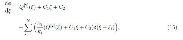
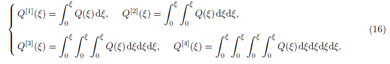
With the properties of the function δ(ξ),the Laplace transform of (15) becomes
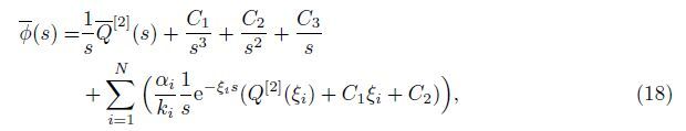
Furthermore,from the second equation of (13),we can obtain
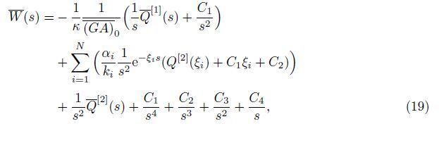
With the inverse Laplace transform,it is easy to obtain
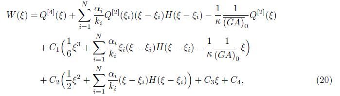
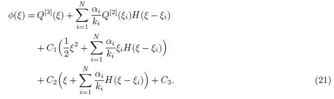
With (10),the dimensionless bending moment m(ξ) and the dimensionless shear force fs(ξ) can be expressed as
Usually,there exist four boundary conditions for a single span beam,which are used to determine the four constants Ci (i = 1,2,3,4). With these boundary conditions,the equation for determining the constants Ci (i = 1,2,3,4) can be expressed as

It should be pointed out that the elements in the matrix A are dependent on the constants Ci (i = 1,2,3,4),because the coefficient αi is dependent on the constants Ci (i = 1,2,3,4),as expressed in (8) and (20)-(22). Therefore,except for several simple cases,it is necessary to use the iteration method to solve (23). Here,given the crack locations ξi,their equivalent rigidity ki,the critical bending moment mi0 (i = 1,2,· · · ,N),and the external load Q(ξ),the following iteration strategy is put forward:
(i) Given the allowance error ε > 0,suppose that all the cracks are open at the initial states, i.e.,αi = αi0 = 1 (i = 1,2,· · · ,N),and denote Ω0 = (α10 ,α20,· · · ,αN0).
(ii) Given Ω1k = (αk,α2k ,· · · ,αNk) (k = 0,1,2,· · · ),solve (23),and obtain the constants Cik (i = 1,2,3,4). Then,use (22) and (8) to compute Ωk+1.
(iii) If ║Ωk+1 - Ωk║ < ε,where ║·║ denotes the Euclidean norm of a vector,then the approximate solution of (23) is obtained,and the bending deformation of the cracked Timoshenko beam is obtained,otherwise go to step (ii) for the next iteration.
It is worth mentioning here that the above iteration calculation is unnecessary for the simple case as shown in the example of Subsection 4.1,in which the coefficient α1 can be determined easily,and the convergence of the above iteration calculations can be achieved within several iterations in the examples of Subsections 4.2 and 4.3 when the allowance error ε = 10-6.
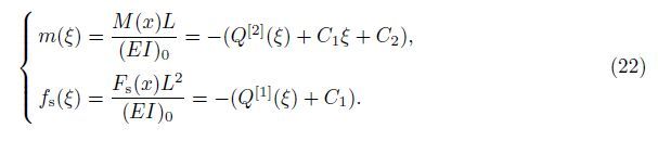
4 ExamplesIn this section,the formulae presented in the preceding section will be applied to three cracked Timoshenko beams to illustrate their bending performances in detail. Suppose that the beam has a rectangular cross section. Then,we have[26]
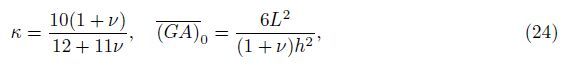
For a crack i with a depth di,the rigidity Ki and its dimensionless equivalent rigidity ki can be expressed as[5, 15, 19]
As shown in Fig. 3,consider a simply-supported Timoshenko beam with a crack subjected to a uniform load q0. The crack with the depth d1 is located on the top surface of the beam at the location x = x1. Denote the dimensionless load and the dimensionless rigidity by Q0 = q0L3/(EI)0 and k1,respectively.

|
| Fig. 3 Simply-supported beam with crack at its top surface |
With the boundary conditions W(0) = W(1) = m(0) = m(1) = 0,we can obtain

Then,the dimensionless deflection,the rotation angle,and the dimensionless bending moment can be expressed as,respectively,


Since the bending moment m1 at the crack location ξ = ξ1 is independent of the constants Ci (i = 1,2,3,4),the iteration method presented above is not needed,and the coefficient α1 can be determined as follows. Suppose that the crack is closed when the rotation angle of the crack reaches θ10. Then,the dimensionless critical couple m10 for the crack closure is m10 = k1θ10.When m1 = m10,the crack is closed,and the critical load Qcr = 2m10/(ξ1(1 - ξ1)) for the crack closure can be obtained from (29). Thus,it has α1 = 1 when Q < Qcr and α1 = m10/m1 when Q ≥ Qcr.
Suppose that the crack is closed when the rotation angle θ1 = θ10 = 1°,and take the location and depth of the crack to be ξ1 = 0.5 and d1/h = 0.5,respectively. The distributions of the deflection W(ξ) and the rotation angle φ(ξ) along the axial line ξ are given in Fig. 4 for different loads Q0 and beam’s slenderness ratios L/h. It can be seen that the deflection W(ξ) and the rotation angle φ(ξ) increase with the load Q0,and there is a cusp on the deflection curve and a jump on the rotation angle curve at the crack location ξ1 = 0.5. Furthermore,when the load Q0 < Qcr,the jump value of the rotation angle φ at the crack location ξ1 = 0.5 increases as the load Q0 increases,while when the load Q0 ≥ Qcr,i.e.,the crack is closed,this jump value remains constant and equals the rotation angle θ10. It should be pointed out that the numerical results also show that these properties are also valid for other values of ξ1 and d1/h.

|
| Fig. 4 Distributions of deflection and rotation angle of simply-supported Timoshenko beam with top surface crack for different loads Q0 and slenderness ratios L/h when ξ1=0.5 and d1/h=0.5 |
The responses of the deflection W0 = W(0.5) at the mid-span of the simply-supported Timoshenko beam versus the load Q0 when ξ1 = 0.5 for different slenderness ratios L/h and crack depths d1/h are presented in Fig. 5,in which the curve with d1/h = 0 corresponds to the deflection of the perfect beam without crack. It is revealed that for the simply-supported Timoshenko beam with a crack at its top surface,i.e.,d1/h ≠ 0,the relation between the deflection W0 and the load Q0 is bilinear. When Q0 < Qcr,the crack is open,and the flexibility between the deflection W0 and the load Q0 is the resultant flexibility of the beam’s flexibility and equivalent rotational spring,which increases with the crack depth d1/h. When Q0 ≥ Qcr, the crack is closed,and the effect of the crack disappears. The flexibility between the deflection W0 and the load Q0 is one of the perfect beam only. Obviously,the flexibility of the beam with the crack closure is less than that of the cracked beam when the crack is open.

|
| Fig. 5 Responses of deflection W0 versus load Q0 of simply-supported Timoshenko beam with crack at its top surface for different slenderness ratios L/h and crack depths d1/h |
The responses of the deflection W0 versus the load Q0 when ξ1 = 0.5 and d1/h = 0.5 for different slenderness ratios L/h are presented in Fig. 6 for the Timoshenko beam and the Euler-Bernoulli beam,respectively. Here,the results for the Euler-Bernoulli beam are obtained by letting $\overline {\left( {GA} \right)} $0→ +∞ in (27). It is shown that the resultant flexibility of the simplysupported beam decreases with the slenderness ratio L/h when the crack is open (Q0 < Qcr). Furthermore,when Q0 ≥ Qcr,different from the response of the Euler-Bernoulli beam,the flexibility of the simply-supported Timoshenko beam does not remain constant and decreases with the slenderness ratio L/h due to the effect of shear deformation.

|
| Fig. 6 Response of deflection W0 versus load Q0 of simply-supported Timoshenko beam with crack at its top surface for different L/h when d1/h=0.5 and ξ1=0.5 |
As shown in Fig. 7,consider a cantilever Timoshenko beam with a bottom surface crack I at x = x1 with the depth d0 and a top surface crack II at x = x2 with the depth d0. The cantilever beam is subjected to a force P0 and a couple T0 at its free end. Denote the dimensionless force and couple by P = P0L2/(EI)0 and T = T0L/(EI)0,respectively.

|
| Fig. 7 Cantilever beam with two cracks |
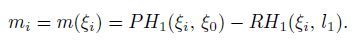
Therefore,it has Q[i](ξ) = 0(i = 1,2,3,4). With the boundary conditions W(0) = φ(0) = 0, fs(1) = P,and m(1) = T,it gets C1 = -P,C2 = P - T,and C3 = C4 = 0. The bending moments m1 = m(ξ1) at the location ξ = ξ1 and m2 = m(ξ2) at the location ξ = ξ2 are
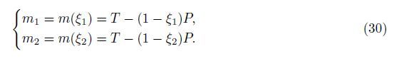
Obviously,the crack I at ξ = ξ1 is closed when m1 = -m10,and the crack II at ξ = ξ2 is closed when m2 = m20. The two conditions give the relations


|
| Fig. 8 Open and close states of cracks in force-couple plane OPT |
Take ξ1 = 0.25,ξ2 = 0.75,θ10 = θ20 = 0.5°,d = d1 = d2,and d/h = 0.5. Then,it has m10 = m20 = m0. Letting T = P/2 and the allowance error ε = 10-6,the iteration numbers for convergence of the preceding iteration processes are less than 6 for different loads (P,T) and beam’s slenderness ratios L/h,and the corresponding distributions of deflection W(ξ) and rotation angle φ(ξ) along the axial line ξ are given in Fig. 9 for different loads (P,T) and beam’s slenderness ratios L/h. It can be seen that the deflection W(ξ) and the rotation angle φ(ξ) increase with the load P,and there are two cusps on the deflection curve and two jumps on the rotation angle curve at the crack locations ξ1 = 0.25 and ξ2 = 0.75. Furthermore,the cusp phenomenon for the short beam is more evident than that for the slender beam.

|
| Fig. 9 Distributions of deflection and rotation angle of cantilever Timoshenko beam with two cracks for different loads P and slenderness ratios L/h |
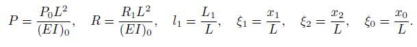
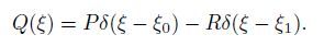
Consider a simply-supported continuous beam with two subspan lengths L1 and L2,subjected to a concentrated force P0 at the locations x = x0 (see Fig. 10). There exist two bottom surface cracks with the depth d1 and d2 at the locations x = x1 and x = x2,respectively. In this case,the load acting on the beam is given by the concentrated force P0 and the reaction R1 at the intermediate support,i.e.,


|
| Fig. 10 Continuous beam with two cracks at bottom surface |
Let L = L1 + L2,and define the dimensionless parameters by
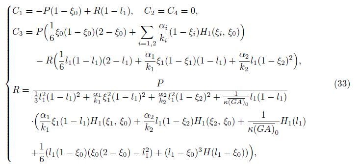
With the boundary conditions W(0) = W(1) = m(0) = m(1) = 0 and a constraint condition W(l1) = 0 at the intermediate support,it gets
The bending moment at the crack ξ = ξi (i = 1,2) is
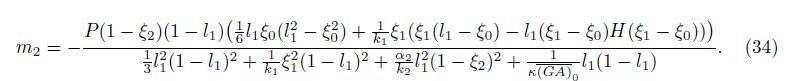
Then,the critical force Pcr for the crack closure at ξ = ξ2 is
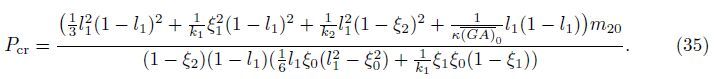
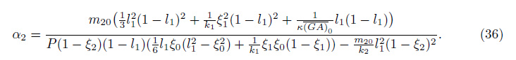
That is,when P < Pcr,the crack at ξ = ξ2 is open,and α2 = 1,while when P ≥ Pcr,the crack at ξ = ξ2 is closed,and
Take ξ0 = 0.125,ξ1 = 0.25,ξ2 = 0.75,l0 = 0.5,θ10 = θ20 = 1°,d = d0 = d0,and d/h = 0.5. Then,it has m10 = m20 = m0. The distributions of the deflection W(ξ) along the axial line ξ of the Timoshenko and Euler-Bernoulli cracked beams are given in Figs. 11(a) and 11(b), respectively,for different concentrated loads P. It can be seen that,for both the Timoshenko and Euler-Bernoulli beams,there are two cusps on the deflection curve at the crack locations ξ1 = 0.25 and ξ2 = 0.75. However,there also exists a cusp on the deflection curve of the Timoshenko beam at the location ξ1 = 0.125. This is because that the transversal shearing force fs of the beam is discontinuous at the location ξ1 = 0.125,and the shearing deformation caused by the shearing force fs induces the additional deflection in the Timoshenko beam model,while for the Euler-Bernoulli beam,there exists no shearing deformation,and therefore, its deflection curve is smooth at the discontinuous shearing force fs.

|
| Fig. 11 Distributions of deflection versus load P of simply-supported continuous beam with two cracks when d/h=0.5 and L/h=5 |
This paper offers a new macro-scale switching crack model which takes account of the effect of the crack gap on the bending analysis of the cracked beam. The crack with a gap is represented by means of an equivalent nonlinear internal rotational spring,i.e.,the crack effect is equivalent to a linear rotational spring when the crack is open,while the crack effect disappears when the crack is closed. The equivalent flexural rigidity for bending of the cracked beam is presented by the generalized Dirac delta function. Then,a closed-form general solution for the static bending of the Timoshenko beam with an arbitrary number of cracks is obtained by the Laplace transform,and a computational strategy for determining the unknown constants is devised. The numerical results are presented for three examples,namely,a simply-supported Timoshenko beam with the top surface crack,a cantilever Timoshenko beam with the top and bottom cracks,and a simply-supported two subspan continuous beam with two bottom cracks. The influence of the beam’s slenderness ratio,the crack’s depth,and the load on the crack states and bending performances of the beam is analyzed,and the following conclusions are obtained.
(i) Based on the Dirac delta function,the closed-form solution for bending of the cracked Timoshenko beam is universal,which can be used for analysis of single beam and multisupported beam.
(ii) The convergence of the iteration strategy for determining unknown constants can be achieved in several iterations in the presented numerical examples for the given allowance error.
(iii) There is a cusp on the deflection curve and a jump on the rotation angle curve at every crack location. Furthermore,the jump value of the rotation angle increases with the load when the crack is open,and this jump value remains constant when the crack is closed.(iv) Generally,the relation between the deflection and the load is bilinear. When the crack is open,the flexibility between the deflection and the load increases with the crack depth, while the flexibility increases as the slenderness ratio decreases. When the crack is closed,the flexibility between the deflection and the load is one of the perfect beam only.
| [1] | Jassim, Z. A., Ali, N. N., Mustapha, F., and Abdul-Jalil, N. A. A review on the vibration analysis for a damage occurrence of a cantilever beam. Engineering Failure Analysis, 31(7), 442-461(2013) |
| [2] | Banan, M. R. and Hjelmstad, K. D. Parameter estimation of structures from static response, I:computational aspects. Journal of Structural Engineering, 120(11), 3243-3258(1994) |
| [3] | Sung, S. H., Koo, K. Y., and Jung, H. J. Modal flexibility-based damage detection of cantilever beam-type structures using baseline modification. Journal of Sound and Vibration, 333(18), 4123-4138(2014) |
| [4] | Dimarogons, A. Vibration of cracked structures:a state of the art review. Engineering Fracture Mechanics, 55(5), 831-857(1996) |
| [5] | Palmeri, A. and Cicirello, A. Physically-based Diraćs delta functions in the static analysis of multicracked Euler-Bernoulli and Timoshenko beams. International Journal of Solids and Structures, 48(14-15), 2184-2195(2011) |
| [6] | Challamel, N. and Xiang, Y. On the influence of the unilateral damage behaviour in the stability of cracked beam columns. Engineering Fracture Mechanics, 77(9), 1467-1478(2010) |
| [7] | Patel, T. H. and Darpe, A. K. Influence of crack breathing model on nonlinear dynamics of a cracked rotor. Journal of Sound and Vibration, 311(3-5), 953-972(2008) |
| [8] | Rezaee, M. and Hassannejad, R. Free vibration analysis of simply supported beam with breathing crack using perturbation method. Acta Mechanica Solida Sinica, 23(5), 459-470(2010) |
| [9] | Buda, G. and Caddemi, S. Identification of concentrated damages in Euler-Bernoulli beams under static loads. Journal of Engineering Mechanics, 133(8), 942-956(2007) |
| [10] | Khaji, N., Shafiei, M., and Jalalpour, M. Closed-form solutions for crack detection problem of Timoshenko beams with various boundary conditions. International Journal of Mechanical Sciences, 51(9-10), 667-681(2009) |
| [11] | Feng, X., Liu, Y. H., and Zhou, J. A method for static deflection analysis for cracked Timoshenko beam (in Chinese). Journal of Disaster Prevention and Mitigation Engineering, 29(6), 652-657(2009) |
| [12] | Caddemi, S. and Calió, I. Exact solution of the multi-cracked Euler-Bernoulli column. International Journal of Solids and Structures, 45(5), 1332-1351(2008) |
| [13] | Li, Q. S. Buckling of an elastically restrained multi-step non-uniform beam with multiple cracks. Archive of Applied Mechanics, 72(6-7), 522-535(2002) |
| [14] | Kisa, M. Vibration and stability of multi-cracked beams under compressive axial loading. International Journal of the Physical Sciences, 6(11), 2681-2696(2011) |
| [15] | Caddemi, S. and Calió, I. Exact closed-form solution for the vibration modes of the Euler-Bernoulli beam with multiple open cracks. Journal of Sound and Vibration, 327(3-5), 473-489(2009) |
| [16] | Caddemi, S. and Calió, I. The influence of the axial force on the vibration of the Euler-Bernoulli beam with an arbitrary number of cracks. Archive of Applied Mechanics, 82(6), 1-13(2012) |
| [17] | Jun, O. S., Eun, H. J., Earmme, Y. Y., and Lee, C. W. Modelling and vibration analysis of a simple rotor with breathing crack. Journal of Sound and Vibration, 155(2), 273-290(1992) |
| [18] | Hu, J. S., Feng, X., and Zhou, J. Study on nonlinear dynamic response of a beam with a breathing crack (in Chinese). Journal of Vibration and Shock, 28(1), 76-80(2009) |
| [19] | Cicirello, A. and Palmeri, A. Static analysis of Euler-Bernoulli beams with multiple unilateral cracks under combined axial and transverse loads. International Journal of Solids and Structures, 51(5), 1020-1029(2014) |
| [20] | Fu, C. Y. The effect of switching cracks on the vibration of a continuous beam bridge subjected to moving vehicles. Journal of Sound and Vibration, 339(3), 157-175(2015) |
| [21] | Bakhtiari-Nejad, F., Khorram, A., and Rezaeian, M. Analytical estimation of natural frequencies and mode shapes of a beam having two cracks. International Journal of Mechanical Sciences, 78(1), 193-202(2014) |
| [22] | Caddemi, S. and Calió, I. The exact explicit dynamic stiffness matrix of multi-cracked Euler-Bernoulli beam and applications to damaged frame structures. Journal of Sound and Vibration, 332(12), 3049-3063(2013) |
| [23] | Caddemi, S., Calió, I., and Marletta, M. The non-linear dynamic response of the Euler-Bernoulli beam with an arbitrary number of switching cracks. International Journal of Non-Linear Mechanics, 45(7), 714-726(2010) |
| [24] | Shen, M. H. H. and Chu, Y. C. Vibration of beams with a fatigue crack. Computers and Structures, 45(1), 79-93(1992) |
| [25] | Gere, J.M. andTimoshenko, S.P. Mechanics of Materials, 2nd SI Edition, van Nostrand Reinhold, New York (1984) |
| [26] | Han, S. M., Benaroya, H., and Wei, T. Dynamics of transversely vibrating beams using four engineering theories. Journal of Sound and Vibration, 225(5), 935-988(1999) |