 2016, Vol. 37
Shanghai University
Article Information
- M. D. NURUL IZYAN, K. K. VISWANATHAN, Z. A. AZIZ, K. PRABAKAR.
- Free vibration of layered cylindrical shells filled with fluid
- Appl. Math. Mech. -Engl. Ed., 2016, 37(6): 803-820
- http://dx.doi.org/10.1007/s10483-016-2089-6
Article History
- Received Nov. 2, 2015;
- Revised Jan. 20, 2016


2. Department of Mathematical Sciences, Faculty of Science, Universiti Teknologi Malaysia, Johor Bahru 81310, Malaysia;
3. Department of Electrical and Computer Engineering, Pusan National University, Busan 609735, South Korea
Laminated composite shell structures are widely used in different industries due to their high stiffness and strength to weight ratios. Circular cylindrical shells filled with fluids are used in pressure vessels and oil tankers. The presence of a liquid in a shell significantly affects the vibration of the shell structure.
Numerous methods and theories have been developed to study the vibrations of the cylindrical shells filled with fluids. Zhang et al.[1] studied the vibration of the fluid filled cylindrical shells by the wave propagation approach and Love’s first-order shell theory. Iqbal et al.[2] presented a paper on the vibration of a functionally graded material (FGM) circular cylindrical shell filled with an incompressible non-viscous fluid by the same method as Zhang et al.[1]. Li[3] investigated the free vibration of the circular cylindrical shell based on Flügge’s classical thin shell theory. Shah et al.[4] studied the circular cylindrical shells filled with a fluid resting on elastic foundations. Natsuki et al.[5] studied the vibration of fluid-filled double walled carbon nano-tubes by the simplified Flügge’s theory.
Goncalves and Batista[6] used the Rayleigh-Ritz technique to study the free vibration of the simply supported vertical cylindrical shells partially filled with or submerged in a fluid with Sanders’ shell theory. Chen and Ding[7] provided the solutions for the free vibration of the transversely isotropic cylindrical shells filled with a fluid by the orthogonal series expansion method. Han and Liu[8] investigated the free vibration of the cylindrical storage tanks partially filled with an inviscid and incompressible fluid through an analytical method with Flügge’s thin shell theory.
Ravikiran and Ganesan[9] examined the free vibration and buckling behavior of the composite cylindrical shells conveying hot fluids under the first-order shear deformation (FSDT) theory and by the finite element method. Lakis et al.[10] reviewed linear and nonlinear vibration analyses of isotropic and anisotropic plates and shells by the hybrid finite element method. The shell equations were derived by Sanders’ shell theory,and the velocity potential and Bernoulli’s equation were adopted to describe the fluid dynamic pressure.
Goncalves et al.[11] used the Galerkin method to study the dynamic behavior of the cylindrical shells filled with fluids with Donnell’s nonlinear shallow shell theory. Paak et al.[12] studied the cantilevered circular cylindrical shells with the quiescent fluid based on Flügge’s shell theory,and modelled the liquid by means of the linearized potential flow theory. Toorani and Lakis[13] used the finite element analysis based on Sanders’ theory,and investigated the vibration characteristics of the anisotropic laminated cylindrical shells partially or completely filled with liquid or subjected to a flowing fluid. Yeo and Lim[14] analyzed the stability of the uniform potential flow over the compliant plates resting on a periodic array foundation by the Fourier transform-based method.
In this paper,we investigate the free vibration of the thin elastic circular cylindrical shells filled with the quiescent fluid by the spline approximation technique. The equations of motion are coupled in the longitudinal,circumferential,and transverse displacement components based on Love’s shell theory. The layers are considered to be thin,elastic,and specially orthotropic or isotropic,and are assumed to be bonded perfectly together and to move without the interface slip[15]. The fluid is assumed to be incompressible and inviscid. By assuming the displacement components in a separable form,a system of coupled differential equations in the displacement functions are obtained. Then,the displacement functions are approximated by the Bickleytype splines,which are cubic and quintic. The collocation with these splines yields a set of field equations together with the equations of boundary conditions. Therefore,it can be reduced to a system of homogeneous simultaneous algebraic equations on the assumed spline coefficients,resulting in a generalized eigenvalue problem. The eigenvalue problem is solved by the eigensolution technique to obtain as many eigenfrequencies as required,starting from the least. Viswanathan et al.[16] studied the free vibration of the symmetric angle-ply laminated circular cylindrical shells by the spline method. With the same method,Viswanathan et al.[17] studied the vibration of the multi-layered circular cylindrical shells with cross-ply walls by the first-order shear deformation theory. Viswanathan et al.[18] analyzed the symmetric angle-ply laminated cylindrical shells of variable thickness by the first-order shear deformation theory. Bickley[19] concluded through his work that the spline chains of low-order approximations yielded better accuracy than a global high-order approximation.
In this paper,we consider two layers of composite elastic shells filled with a fluid by different types of materials such as S-glass epoxy (SGE),high strength graphite epoxy (HSG),and PRD- 490 III epoxy (PRD). The parametric studies are made to investigate the effects of the relative layer thickness,the length-to-radius ratio,the length-to-thickness ratio,and the circumferential node number on the frequency parameters under clamped-clamped (C-C) and simply supported (S-S) boundary conditions. This spline is simple and elegant since it gives accurate results with the past literature. The results are presented in terms of graphs and tables.
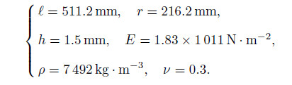
Consider a thin composite layered circular cylindrical shell with the length ℓ,the constant thickness h,and the radius r. Each layer is assumed to be homogeneous,linearly elastic,and isotropic or specially orthotropic. The x-coordinate of the shells is taken along the longitudinal direction,and the θ- and z-coordinates are in the circumferential direction and the radial direction,respectively. The equations of motion for the cylindrical shells are based on Love’s shell theory[16, 20]. The equations of the cylindrical shells filled with a fluid are given as follows[21]:

where t is the time,p is the pressure,ρ is the density,and h is the thickness of the cylinder.
The stress resultants and the stress couples are

where Nx,Nθ,and Nxθ are the stress resultants,Mx,Mθ,and Mxθ are the moment resultants,and σx,σθ,and τxθ are the stresses in the respective directions,respectively.
The strain-displacement relations of the circular cylindrical shells are

where u,v,and w are the displacement functions of the midplane in the longitudinal,circumferential,and transverse directions,respectively.
For a thin laminated cylindrical shell,the stress-strain relations of the kth layer are defined by

Substituting Eq. (3) into Eq. (4) and then substituting the obtained result into Eq. (2),we can obtain the force and moment resultants as follows:

where A11,A12,A22,A66,B11,B12,B22, B66,and D11,D12,D22,D66 are the extensional rigidities,the bending-stretching coupling rigidities,and the bending rigidities defined by

zk is the distance from the midsurface to the surface of the kth layer. For a thin shell,Q11k ,Q12k,Q12k,and Q66k are reduced to the stiffnesses defined by

Substituting Eq. (5) into Eq. (1) yields the equations of equilibrium in terms of the u,v,and w displacements as follows:

where Lij (i,j = 1,2,3) are differential operators given in Appendix A.
The displacement components u,v,and w are assumed as follows:

where x and θ are the longitudinal coordinate and the rotational coordinate,respectively,ω is the angular frequency of the vibration,t is the time,and n is the circumferential node number.
2.2 Fluid structure interaction equationsThe fluid is assumed to be incompressible. The irrotational flow of an inviscid fluid undergoing small oscillations is expressed as a wave equation. The equation of motion of the fluid can be written in the cylindrical coordinate system (x,θ,r) as follows[1, 2]:

where t is the time,p is the pressure,and c is the sound speed of the fluid. The x- and θ- coordinates are the same as those of the shell,while the r-coordinate is taken from the x-axis of the shell.
The associated form of the pressure field in the contained fluid,satisfying Eq. (10),is assumed to be

where Jn is the Bessel function of the order n.
The fluid radial displacement and the shell radial displacement must be equal at the interface of the shell inner wall and the fluid in order to ensure that the fluid remains in contact with the shell wall. Then,the coupling condition is[1, 2]

Therefore,we have

where ρf is the density of the contained fluid,and the prime on Jn denotes differentiation with respect to the argument r.
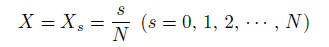
Introduce the following non-dimensional parameters:

where L is the length,X is the distance coordinate,R is the radius,H is the thickness,λ is the frequency,and δk is the relative thickness of the kth layer.
Substituting Eq. (9) into Eq. (8) together with Eq. (11) and then using the non-dimensional parameters,we can obtain the equation of motion of the coupled system in the symmetric form as follows:

where Lij (i,j = 1,2,3) are the differential operators given in Appendix B.
Since the third column of Eq. (15) contains the derivatives of the third-order in U,the form of Eq. (15) is not convenient to the solution procedure we propose to adopt. Therefore,the equations are combined within themselves,and a modified set of equations are derived. To modify the equations,the first column of Eq. (15) is differentiated with respect to X and used to eliminate U′′′(X) in the third equation. The modified set of equations are given by

where L31* ,L32*,and L33* are the updated differential operators given in Appendix C.
3 Solution procedure 3.1 Bickley-type methodThe spline approximation is a lower order approximation,which yields a better accuracy than a global higher order approximation. Bickley[19] successfully tested the spline collocation method over a two point boundary value problem with cubic splines. The displacement functions U(X),V (X),and W(X) are approximated by the cubic and quintic spline functions U*(X),V*(X),and W*(X) as follows:

where H(X −Xj) is the Heaviside step function,and N is the number of intervals in the range of X ∈ [0, 1]. The division points
are chosen as the knots of the splines as well as the collocation points. Imposing the condition that the differential equations given by Eq. (16) are satisfied by these splines at the knots,we can obtain a set of 3N +3 homogeneous equations into 3N +15 unknown spline coefficients ai,bj,ci,dj , ei,and fj (i = 0,1,2,3,4; j = 0,1,2,· · · ,N − 1).
3.2 Boundary conditionsThe following boundary conditions are used to analyze the problem:
(i) C-C

(ii) S-S

From any of the boundary conditions,we can obtain eight more equations on the spline coefficients. Combining these eight equations with the earlier 3N + 3 homogeneous equations,we can get 3N + 15 homogeneous equations with the same number unknowns. Thus,these equations can be reduced to a system,which can be written as follows:

where M and P are square matrices,q is a column matrix of the spline coefficients,and λ is the frequency parameter. This is a generalized eigenvalue problem.
4 Results and discussion 4.1 Convergence and comparative studiesThe convergence study for the frequency parameter is carried out under the C-C boundary condition. The values of N are started from

onwards. From Table 1,we can see that the choice of
 |

is sufficient,since the computed values of λ improve with the increase in N,but the improvement come down steadily when

Comparisons of the results are made in order to verify the efficiency of the present method. Table 2 shows a non-dimensional frequency for the isotropic cylindrical shells filled with a fluid under the C-C boundary condition. The results are compared with those in Refs. [1] and [2]. From Table 2,we can see that the present results agree well with those obtained in Refs. [1] and [2]. Some values in our case are a little higher. This may be due to the different material properties and the different adopted method.
 |
In Table 3,the used parametric values are
 |
The natural frequencies under the C-C boundary condition for
are compared with those obtained in Refs. [22],[23],and [24] (see Table 3).
In this work,the frequency parameter is analyzed for two layered cylindrical shells filled with a fluid. The considered materials are HSG,SGE,and PRD. The variations of the frequency parameters with respect to the thickness ratio (δ),the length of cylinder (L),the thickness of cylinder (H),and the circumferential node number (n) under the C-C and S-S boundary conditions are studied.
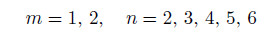
The variations of the frequency parameters λm (m = 1,2,3) with respect to the ratio of the thickness of the inner layer to the entire thickness δ under the C-C boundary condition and HSG-PRD are depicted in Fig. 1. From Fig. 1,we can see that,when δ = 0,the shell becomes a homogeneous PRD shell; when δ = 1,the shell becomes a homogenous HSG shell; when 0 < δ < 1,both layers exist. From Fig. 1,we can see that λ1,λ2,and λ3 increase with the increase in δ. However,when the value of δ is between 0 and 0.2,λ2 and λ3 increase rapidly,while λ1 increases slowly.
 |
| Fig. 1 Variations of frequency parameters with respect to relative layer thickness under C-C bound- ary condition and HSG-PRD, where n = 2, and H = 0.02 |
Figure 2 describes the variations of the frequency parameters λ1,λ2,and λ3 with respect to the ratio of the thickness of the inner layer to the entire thickness δ (0 < δ < 1) under HSG-PRD and the C-C boundary condition. From Fig. 2,we can see that,when δ = 0,the shell becomes a homogeneous PRD shell; when δ = 1,the shell becomes a homogenous HSG shell; when 0 < δ < 1,both layers exist. It can be seen that,when δ increases from 0 to 0.2,λ1 increases gradually,while λ2 and λ3 increase rapidly. From Fig. 2(a),we can see that λ1,λ2,and λ3 increase slowly when 0.2 < δ < 1. The nature of the curves in Fig. 2(b) is almost identical to those in Fig. 2(a). It can be observed that the values of λ1,λ2,and λ3 in Fig. 2(b) are smaller than those obtained in Fig. 2(a) when δ = 0.
 |
| Fig. 2 Variations of frequency parameters with respect to relative layer thickness under C-C bound- ary condition and HSG-PRD, where n = 2, and H = 0.05 |
Figure 3 shows the variations of the frequency parameters λ1,λ2,and λ3 with respect to the ratio of the thickness of the inner layer to the entire thickness δ under HSG-SGE and the C-C boundary condition. From Fig. 3,we can see that ,when δ = 0,the shell becomes a homogeneous SGE shell; when δ = 1,the shell becomes a homogenous HSG shell; when 0 < δ < 1,both layers exist. From Fig. 3(a),we can see that λ1,λ2,and λ3 change with the increase in δ. λ1 decreases slowly when 0 ≤ δ ≤ 0.6,and then increases gradually afterwards. λ2 and λ3 increase rapidly when 0 ≤ δ ≤ 0.2,decrease slowly when 0.2 ≤ δ ≤ 0.6,and increase gradually afterwards. From Fig. 3(b),we can see that λ1,λ2,and λ3 change with the increases in δ. The pattern variations for λ1 and λ3 are similar to those obtained in Fig. 3(a). λ2 slowly decreases when 0 ≤ δ ≤ 0.6,and gradually increases when δ > 0.6.
 |
| Fig. 3 Variations of frequency parameters with respect to relative layer thickness under C-C bound- ary condition and HSG-SGE, where n = 4, and H = 0.02 |
Figure 4 corresponds to the effects of the length parameter L on ω1,ω2,and ω3 of the cylindrical shells under HSG-SGE and the C-C boundary condition. Since λm is explicitly a function of the length of the cylinder,when studying the effect of the length of the cylinder on its vibrational behavior,the angular frequency ωm (×103 Hz) is considered instead of λm. From Fig. 4(a),we can see that ω1,ω2,and ω3 decrease smoothly when L increases,and the decreases are fast when 0 < L < 0.75 while slow when 0.75 < L < 2. From Fig. 4(b),we can see that the pattern variations of ω1,ω2,and ω3 are the same as those obtained in Fig. 4(a).
 |
| Fig. 4 Effects of length on angular frequency under C-C boundary condition and HSG-SGE, where H = 0.02, and δ = 0.4 |
Figure 5 describes the effects of the thickness parameter H on λ1,λ2,and λ3 under HSGSGE and the C-C boundary condition. From Fig. 5(a),we can see that λ1,λ2,and λ3 increase slowly when 0.01 ≤ H ≤ 0.02. When 0.02 < H < 0.06,λ3 increases rapidly,while λ1 and λ2 increase slowly. The values of λm (m = 1,2,3) are higher for higher modes. From Fig. 5(b),we can see that the patterns of the variations of λ1,λ2,and λ3 are similar to those obtained in Fig. 5(a).
 |
| Fig. 5 Effects of thickness parameter on frequency parameters under C-C boundary condition and HSG-SGE, where L = 1.25, and δ = 0.4 |
The effects of the circumferential node number n on λ1,λ2,and λ3 under the C-C boundary condition and HSG-SGE and HSG-PRD are shown in Figs. 6(a)-6(d). From Fig. 6(a),we can see that λ1,λ2,and λ3 increase rapidly when 1 ≤ n ≤ 2. After that,λ2 slowly decreases until n = 5,λ1 slowly decreases when 1 ≤ n ≤ 5,while λ3 increases gradually. When 5 < n < 6,λ1,λ2,and λ3 increase rapidly. From Fig. 6(b),we can see that there are rapid increases in λ2 and λ3 when 1 ≤ n ≤ 2. After that,λ2 increases slowly until n = 5. When 5 < n < 6,λ1,λ2,and λ3 increase rapidly. From Fig. 6(c),we can see that the patterns of the variations of λ1,λ2,and λ3 are similar to those obtained in Fig. 6(a). However,when n = 1,the values of λ1,λ2,and λ3 are smaller than those in Fig. 6(a). This is because of the applied different combination of materials. The variation nature of λ1,λ2,and λ3 in Fig. 6(d) are the same as those in Fig. 6(b). However,the values of λ1,λ2,and λ3 when n = 1 are smaller than those in Fig. 6(b). This is due to the different combination of the materials.
 |
| Fig. 6 Variations of frequency parameters with respect to circumferential node number under C-C boundary condition and HSG-SGE or HSG-PRD |
Figure 7 shows the variations of the frequency parameters λ1,λ2,and λ3 with respect to the ratio of the thickness of the inner layer to the entire thickness δ under the S-S boundary condition and HSG-PRD. From Fig. 7,we can see that,when δ = 0,the shell becomes a homogeneous PRD shell; when δ = 1,the shell becomes a homogenous HSG shell; when 0 < δ < 1,both layers exist. λ1,λ2,and λ3 increase with the increase in δ. However,λ2 and λ3 increase faster than λ1. It can also be observed that the frequencies for all modes in Fig. 7(b) are higher than those in Fig. 7(a).
 |
| Fig. 7 Variations of frequency parameters with respect to relative layer thickness under S-S boundary condition and HSG-PRD, where n = 2, and H = 0.02 |
Figure 8 depicts the variations of λ1,λ2,and λ3 with respect to the ratio of the thickness of the inner layer to the entire thickness δ under HSG-PRD and the S-S boundary condition. From Fig. 8,we can see that,when δ = 0,the shell becomes a homogeneous PRD shell; when δ = 1,the shell becomes a homogenous HSG shell; when 0 < δ < 1,both layers exist. It can be observed that,when 0 ≤ δ ≤ 0.2,λ1 increases gradually,while λ2 and λ3 increase rapidly. After that,λ1,λ2,and λ3 increase slowly when δ increases.
 |
| Fig. 8 Variations of frequency parameters with respect to relative layer thickness under C-C bound- ary condition and HSG-PRD material, where n = 2, and H = 0.05 |
Figure 9 exhibits the variations of the frequency parameters λ1,λ2,and λ3 with respect to the ratio of the thickness of the inner layer to the entire thickness δ under HSG-SGE and the S-S boundary condition. From Fig. 9,we can see that,when δ = 0,the shell becomes a homogeneous SGE shell; when δ = 1,the shell becomes a homogenous HSG shell; when 0 < δ < 1,both layers exist. From Fig. 9(a),we can see that λ1,λ2,and λ3 change with the increase in δ. λ1 increases gradually when 0 < δ < 0.2,and decreases slowly afterwards. λ2 and λ3 rapidly increase when 0 6 δ 6 0.2. λ2 decreases slowly when 0.2 < δ < 0.8,and after that increases gradually. λ3 rapidly decreases when 0.2 ≤ δ ≤ 0.8,while increases significantly afterwards. From Fig. 9(b),we can see that,λ1,λ2,and λ3 change with the increase in δ. λ1 decreases when 0 < δ < 1. λ2 and λ3 rapidly increase when 0 ≤ δ ≤ 0.2,then decrease slowly when 0.2 ≤ δ ≤ 0.8,and increase gradually when δ > 0.8.
 |
| Fig. 9 Variations of frequency parameters with respect to relative layer thickness under S-S boundary condition and HSG-SGE, where n = 4, and H = 0.02 |
Figure 10 describes the variations of ω1 (×103 Hz),ω2 (×103 Hz),and ω3 (×103 Hz) of the cylindrical shells with respect to the length parameter under HSG-SGE and the S-S boundary condition. From Fig. 10,we can see that,when L increases,ω1,ω2,and ω3 decrease smoothly. However,the decreases are fast when 0 < L < 0.75 while slow when 0.75 > L > 2. Besides,the values of the frequencies obtained under the S-S boundary condition are lower than those under the C-C boundary condition.
 |
| Fig. 10 Effects of length on angular frequency under S-S boundary condition and HSG-SGE, where H = 0.02, and δ = 0.4 |
Figure 11 shows the variations of λ1,λ2,and λ3 in the thickness parameter H under HSGSGE and the S-S boundary condition. From Fig. 11,we can see that λ1,λ2,and λ3 increase smoothly when H increases. From Fig. 11(a),we can see that,λ1 is almost constant for all values of H. λ2 and λ3 increase slowly when 0.01 ≤ H ≤ 0.02. After that,λ3 increases rapidly when 0.02 < H < 0.06,while λ2 increases slowly. From Fig. 11(b),we can see that,λ1,λ2,and λ3 increase when H increases.
 |
| Fig. 11 Effects of thickness parameter on frequency parameters under S-S boundary condition and HSG-SGE, where n = 2, and δ = 0.4 |
Figure 12 shows the effects of n on λ1,λ2,and λ3 under HSG-SGE and the S-S boundary condition. From Fig. 12(a),we can see that λ1 decreases while λ2 and λ3 increase rapidly when 1 ≤ n ≤ 2. After that,λ1 and λ2 slowly decrease until n = 5,while λ3 increases gradually. When 5 < n < 6,λ1,λ2,and λ3 increase rapidly. From Fig. 12(b),we can see that,λ1 decreases while λ2 and λ3 increase when 1 ≤ n ≤ 2. After that,λ1 and λ2 slowly decrease until n = 5,λ2 and λ3 decrease first,then increase slowly,while λ3 increases gradually. When 5 < n < 6,λ1,λ2,and λ3 increase rapidly.
 |
| Fig. 12 Variations of frequency parameters with respect to circumferential node number under S-S boundary condition and HSG-SGE, where L = 1.25, and δ = 0.4 |
The vibrations of the laminated cylindrical shells filled with a quiescent,incompressible,and inviscid fluid based on Love’s shell theory are studied. The Bickley-type spline is used to approximate the displacements,and the eigenvalue problem is solved for finding the frequency parameters. The spline method has very attractive characteristics for the computational work in terms of the convergence and accuracy,comparing with the finite element method and the wave propagation method[1, 2]. Three types of materials are used in the analysis. The effects of the relative layer thickness,the length to thickness ratio,the length to radius ratio,and the circumferential node numbers on the frequency parameters of two layered cylindrical shells filled with a fluid under C-C and S-S boundary conditions are analyzed.
It is concluded that the fluid in the cylindrical shells strongly affects the frequency parameters. It is observed that the frequency parameters of the cylindrical shells filled with the fluid give lower values than the cylindrical shells without the fluid[15]. The frequency parameter decreases when L increases. The effects of the thickness on the frequency parameter show that the frequency parameter increases when the thickness parameter increases. Besides,the frequency parameter increases when the circumferential node number increases. The values for all the frequencies obtained under the C-C boundary condition are higher than those under the S-S boundary condition. Therefore,it depends on the chosen material and parameters. The analysis can be extended to study other aspects such as shell structures with flowing fluids.
| [1] | Zhang, X., Liu, G., and Lam, K. Coupled vibration analysis of fluid filled cylindrical shells using the wave propagation approach. Applied Acoustics, 62, 229-243 (2001) |
| [2] | Iqbal, Z., Naeem, M. N., Sultana, N., Arshad, S. H., and Shah, A. G. Vibration characteristics of FGM circular cylindrical shells filled with fluid using wave propagation approach. Applied Mathematics and Mechanics (English Edition), 30(11), 1393-1404 (2009) DOI 10.1007/s10483-009-1105-x |
| [3] | Li, X. B. Study on free vibration analysis of circular cylindrical shells using wave propagation. Journal of Sound and Vibration, 311, 667-682 (2008) |
| [4] | Shah, A. G., Mahmood, T., Naeem, M. N., and Arshad, S. H. Vibration characteristics of fuid filled cylindrical shells based on elastic foundations. Acta Mechanica, 216, 17-28 (2011) |
| [5] | Natsuki, T., Ni, Q. Q., and Endo, M. Vibrational analysis of fluid-filled carbon nano-tubes using the wave propagation approach. Applied Pyhsics A, 90, 441-445 (2008) |
| [6] | Goncalves, P. B. and Batista, R. C. Frequency response of cylindrical shells partially submerged or filled with liquid. Journal of Sound and Vibration, 113, 59-70 (1987) |
| [7] | Chen, W. and Ding, H. Natural frequencies of fluid-filled transversely isotropic cylindrical shells. International Journal of Mechanical Sciences, 41, 677-684 (1999) |
| [8] | Han, R. P. S. and Liu, J. D. Free vibration analysis of a fluid-loaded variable thickness cylindrical tank. Journal of Sound and Vibration, 176, 235-253 (1994) |
| [9] | Ravikiran, K. and Ganesan, N. Free Vibration and buckling analysis of composite cylindrical shells conveying hot fluid. Composite Structures, 60, 19-32 (2003) |
| [10] | Lakis, A. A., Toorani, M. H., Kerboua, Y., Esmailzadeh, M., and Sabri, F. Theory, analysis and design of fluid-shell structures. Tech Science Press, 6, 155-185 (2011) |
| [11] | Goncalves, P. B., da Silva, F. M. A., Z., and del Prado, J. G. N. Transient stability of empty and fluid filled cylindrical shells. Journal of the Brazil Society of Mechanical Sciences and Engineering, 3, 331-338 (2006) |
| [12] | Paak, M., Paidoussis, M. P., and Misra, A. K. Nonlinear vibrations of cantilevered circular cylin-drical shells in contact with quiescent fluid. Journal of Fluids and Structures, 49, 283-302 (2014) |
| [13] | Toorani, M. H. and Lakis, A. A. Dynamics behavior of axisymmetric and beam-like anisotropic cylindrical shells conveying fluid. Journal of Sound and Vibration, 259, 265-298 (2003) |
| [14] | Yeo, K. S. and Lim, C. W. The stability of flow over periodically supported plates-potential flow. Journal of Fluids and Structures, 8, 331-354 (1994) |
| [15] | Viswanathanan, K. K. and Navaneethakrishnan, P. V. Free vibration study of layered cylindrical shells by collocation with splines. Journal of Sound and Vibration, 260, 807-827 (2003) |
| [16] | Viswanathan, K. K., Lee, J. H., Aziz, Z. A., and Hossain, I. Free vibration of symmetric angle-ply laminated circular cylindrical shells of variable thickness. Acta Mechanica, 221, 309-319 (2014) |
| [17] | Viswanathan, K. K., Kim, K. S., Lee, J. H., Koh, H. S., and Lee, J. B. Free vibration of multi-layered circular cylindrical shell with cross-ply walls including shear deformation by using spline function method. Journal of Mechanical Science and Technology, 22, 2062-2075 (2008) |
| [18] | Viswanathan, K. K., Javed, S., Aziz, Z. A., and Hossain, I. Free vibration of symmetric angle-ply laminated cylindrical shells of variable thickness including shear deformation theory. International Journal of the Physical Sciences, 6, 6098-6109 (2011) |
| [19] | Bickley,W. G. Piecewise cubic interpolation and two point boundary problems. Computer Journal, 11, 206-208 (1968) |
| [20] | Soedel, W. Vibrations of Shells and Plates, Marcel Dekker, Inc., New York (2004) |
| [21] | Paidoussis, M. P. Fluid-Structure Interactions, Academic Press, London (2004) |
| [22] | Arnold, R. N. and Warburton, G. B. Flexural vibrations of the walls of thin cylindrical shells having freely supported ends. Proceedings of the Royal Society A: Mathematical, Physical and Engineering Science, 197, 238-256 (1949) |
| [23] | Smith, B. L. and Haft, E. E. Natural frequencies of clamped cylindrical shells. Journal of Aeronautics and Astronautics, 6, 720-721 (1968) |
| [24] | Au-Yang, M. K. Natural frequency of cylindrical shells and panels in vacuum and in a fluid. Journal of Sound and Vibration, 57, 341-355 (1978) |