 2016, Vol. 37
Shanghai University
Article Information
- M. HAJHOSSEINI, M. RAFEEYAN
- Modeling and analysis of piezoelectric beam with periodically variable cross-sections for vibration energy harvesting
- Applied Mathematics and Mechanics (English Edition), 2016, 37(8): 1053-1066.
- http://dx.doi.org/10.1007/s10483-016-2117-8
Article History
- Received Jan. 27, 2016
- Revised Apr. 22, 2016


In recent years,a lot of studies have been done on the vibration energy harvesting using piezoelectric materials[1-2]. The voltage generated by the piezoelectric materials is directly proportional to the strain. Therefore,the voltage output will reach the peak value only at the resonant frequency. Two main methods have been studied to solve this problem[3]. The first one is to adjust the resonant frequency of the energy harvester so that it can match the main frequency of the ambient vibration at all times. Eichhorn et al.[4] presented a cantilever tunable energy harvester by applying the prestress at its free end. Reissman et al.[5] demonstrated a tuning technique using the variable attractive magnetic force. Zhu et al.[6] proposed a similar setup to the one of Ref. [5],but they further implemented an automatic controller for resonance tuning. The other method is to design a broadband harvester. Shahruz[7] designed an energy harvester that consists of piezoelectric cantilevers of various lengths and tip masses attached to a common base. It was capable of resonating at various frequencies by properly selecting the length and tip mass of each beam and thus provided the voltage response over a wide frequency range.
Structures with periodic properties for both material and geometrical parameters have a lot of features. A peculiar feature of periodic structures is called as band gaps. Band gaps are defined as frequency intervals where elastic waves are forbidden from propagating. This is of interest for applications such as frequency filters,noise control,and absorption of vibration[2, 8].
In this study,a bimorph piezoelectric cantilever beam with periodically variable crosssections is used for vibration energy harvesting. Two geometrical parameters are defined for this periodic beam,and their effects on the width and central frequency of the first band gap are investigated by the generalized differential quadrature rule (GDQR) method. The GDQR method is also used to calculate the forced vibration response of the beam and voltage of each piezoelectric layer when the beam is subjected to a sinusoidal base excitation. Results obtained from the analytical method are compared with those obtained from the ANSYS software. The voltage output of this periodic beam over its first band gap is calculated and compared with the voltage output of the uniform piezoelectric beam. Finally,the advantages of this new scheme over the uniform piezoelectric beam are mentioned.
2 Periodic beam modelThe new scheme introduced for vibration energy harvesting is shown in Fig. 1.

|
| Fig. 1 Proposed scheme |
|
|
Each periodic structure consists of an infinite repetition of the unit cells. In this study,the unit cell shown in Fig. 2 is considered for the proposed scheme.

|
| Fig. 2 Unit cell |
|
|
This cell contains two multilayer beam elements. When the length of each element is much greater than its height,it can be regarded as an Euler-Bernoulli beam. The governing equation of an Euler-Bernoulli beam is written as follows[9]:

Therefore,the governing equation for the free vibration of the ith beam element is given

In addition,as the system consists of two different materials,the terms (ρA)(i) and (EI)(i) arewritten as[10]

where E is the Young’s modulus of the beam,A is the cross-section area,ρ is the beam density,I is the second area moment of inertia about the neutral axis,b is the width of the beam,W is the mode shape,and x(i) is the local coordinate. Also,M = 2 × Nu,and Nu is the number of unit cells. Subscripts p and np refer to the piezoelectric and non-piezoelectric materials,respectively.
At the junction of the two adjacent elements,the continuity of deflection,slope,moment,and shear force can be written as,respectively,

According to the Bloch-Floquet theorem[11],the deflection,slope,moment,and shear force obey a periodic law and can be written as,respectively,

where a = L(1) + L(2) is the length of the unit cell,and kx is the wave vector in the x-direction. By solving the governing equation (2) and boundary equations (4) and (5),the band gaps of this periodic structure are calculated.
As shown in Fig. 3,the periodic structure is subjected to a sinusoidal base excitation,where Wf is the amplitude of the forced vibration response,wb is the base excitation,w0 is the amplitude of the base,and ωf is the frequency of the base excitation. Therefore,its steady state response can be considered as follows:


|
| Fig. 3 Periodic structure subjected to sinusoidal base excitation |
|
|
Substituting Eq. (6) into Eq. (1),the governing equation for the forced vibration of the ith beam element is given as follows:

At the junction of the two adjacent elements,the continuity of deflection,slope,moment,and shear force can be preserved as

The boundary conditions at the two ends of this periodic structure are written as follows:

By solving the governing equation (7) and boundary equations (8) and (9),the forced vibration response of this periodic structure is calculated. Results obtained from the forced vibration analysis can be used to calculate the voltage of each piezoelectric layer.
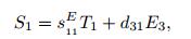
The piezoelectric constitutive equations are written as follows[12]:
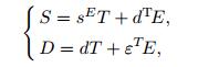 (10)
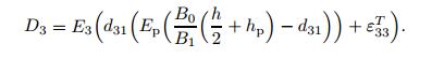
(10) where S is the strain,T is the stress,s is the compliance matrix,d is the piezoelectric coupling coefficient,E is the electric field,D is the electric displacement,and ε is the permittivity. Also,the superscripts E and T denote that the respective constants are evaluated at the constant electric field and constant stress,and the superscript T stands for the transpose.
In the Euler-Bernoulli beam theory,the stress components other than the one-dimensional bending stress T1 are negligible,therefore,T2 = T3 = T4 = T5 = T6 = 0. Along with this simplification,if an electrode pair covers the faces perpendicular to the z-direction (E1 = E2 = 0),Eq.(10) becomes
 (11a)
(11a) 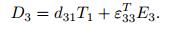 (11b)
(11b) Figure 4 shows a beam element in this structure. If the radius of curvature of the beam element is much larger than its height,the relation between the strain and curvature of the beam can be expressed as follows:
 (12)
(12) where R is the radius of curvature,and z is the distance from the neutral axis.
By using Eqs. (11a) and (12),the stresses in the piezoelectric and non-piezoelectric materials can be obtained as
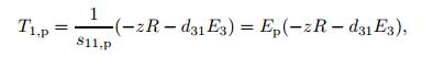 (13a)
(13a) 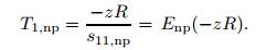 (13b)
(13b) Also,if the piezoelectric layers are poled in the same directions,the device is said to be in the parallel connection (E3 = V/hp)[13]. For this connection,a common ground must be introduced.
The internal moment of the beam element can be written as
 (14)
(14) where
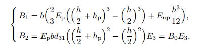 (15)
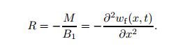
(15) In the inverse piezoelectric effect (M = 0),the radius of curvature is
 (16)
(16) By using Eqs. (11b),(13a),(15),and (16),the electric displacement at the upper surface of the piezoelectric layer is expressed as
 (17)
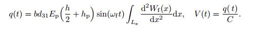
(17) The electric charge,q,is obtained by integrating the electric displacement over the electrode area,
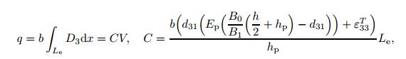 (18)
(18) where V is the voltage,Le is the length of the electrode,and C is the capacitance.
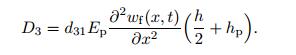
In the direct piezoelectric effect (E3 = 0),and when the beam vibrates,the radius of the curvature is defined as
 (19)
(19) By using Eqs. (11b),(13a),and (19),the electric displacement at the upper surface of the piezoelectric layer is expressed as
 (20)
(20) Finally,the electric charge and voltage of the piezoelectric layer are obtained as
 (21)
(21) In the next section,we will show how the GDQR method is used for the vibration band gap and forced vibration analysis of this periodic structure to calculate the voltage of each piezoelectric layer.
3 GDQRThe differential quadrature method (DQM) was proposed by Bellman and Casti[14]. The basic concept of the DQM is that the derivative of a function at a given point can be approximated as a weighted linear sum of the functional values at all sample points in the domain of that variable. Using this approximation,the differential equation is then reduced to a set of algebraic equations.
Usually,the fourth-order differential equations in structural mechanics such as the displacement of beam and plate,buckling and free-vibration analysis have two boundary equations at each boundary. Two conditions at the same point provoke a real challenge for the classic DQM,because in the classic DQM we have only one quadrature equation at one point,but two boundary equations are to be implemented[15-16]. Wu and Liu[17] proposed the GDQR and also introduced multiple degrees of freedom at boundary points. For example,in vibration analysis of the beam,the first derivatives at the boundary points are viewed as additional independent variables.
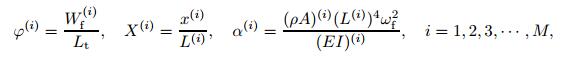
3.1 Vibration band gap analysisIn order to apply the GDQR conveniently and improve the numerical robust,all equations involved should be normalized. For the band gap analysis,the dimensionless parameters are defined as follows:
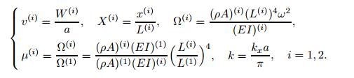 (22)
(22) By taking the equal grid points for two beam elements X(1) = X(2) = X,the rth derivative of the function v(i) at the grid point Xm is defined as follows[17]:
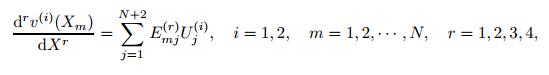 (23)
(23) where Uj(i) are the independent variables for the ith beam element and defined as follows:
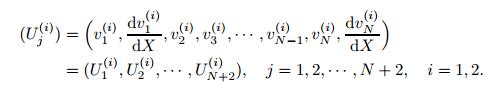 (24)
(24) Emj(r) are the GDQR weighting coefficients for the rth order derivative and calculated by Wu and Liu[17]. N is the number of grid points. The cosine type sampling points in the normalized interval [0,1] will be employed in this work. Their advantage has been discussed in Ref. [18],
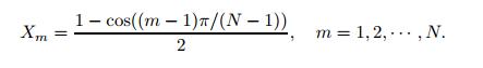 (25)
(25) By using the dimensionless parameters and Eq. (23),the governing equation (2) at the ith beam element inner points,Xm,can be written as follows:
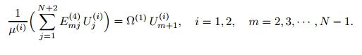 (26)
(26) Also,by using the dimensionless parameters and Eq. (23),the boundary equations (4) and (5) are,respectively,written as follows:
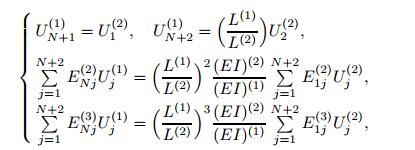 (27)
(27) 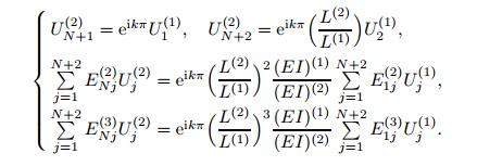 (28)
(28) Together with eight boundary conditions and 2(N − 2) governing equations at the elements inner points,2(N + 2) algebraic equations are obtained. The total number of independent variables (Uj(i)) is also 2(N + 2). By rearranging Eqs. (26),(27),and (28),the assembled form is
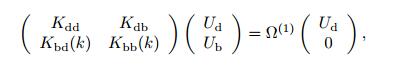 (29)
(29) where the subscripts d and b refer to the values at the domain and boundary grid points,respectively,
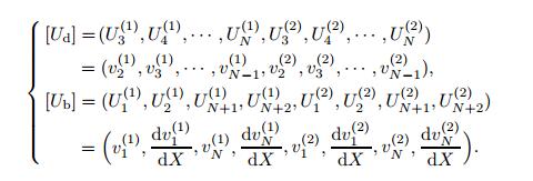 (30)
(30) By substructuring and manipulating the matrix,one can obtain a standard eigenvalue equation,
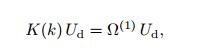 (31)
(31) where K(k) = Kdd − KdbKbb −1(k)Kbd(k). Finally,by calculating the eigenvalues of Eq. (31),the relationship between the angular frequency ω and the wave vector k can be obtained,i.e.,the band gaps. The wave vector k is only selected over the first Brillouin zone (see Ref. [11]),i.e.,k ∈ [−1,1].
3.2 Forced vibration analysisFor the forced vibration analysis,the dimensionless parameters are defined as
 (32)
(32) where Lt is the total length of the periodic structure. The grid points can be different for each beam element. In this study,the equal grid points for all beam elements are considered as X (1) = X (2) = · · · = X (M) = X. By using the dimensionless parameters and Eq. (23),the governing equation (7) at the ith beam element inner points,Xm,can be written as follows:
 (33)
(33) where
 (34)
(34) Also,by using the dimensionless parameters and Eq. (23),the boundary equations (8) and (9) are,respectively,written as follows:
 (35)
(35)  (36)
(36) Together with (4(M −1)+4) boundary conditions and M(N −2) governing equations at the elements inner points,M(N + 2) algebraic equations are obtained. The total number of independent variables (Yj(i)) is also M(N +2). Finally,by solving the algebraic equations,Eqs. (33),(35),and (36),the forced vibration response (Yj(i)) of the periodic structure is calculated.
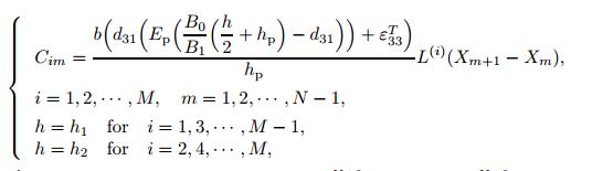
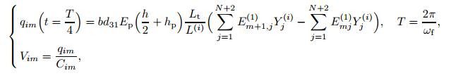
3.3 Voltage of each piezoelectric layerAs shown in Fig. 4,we assume that the electrodes are mounted between the two adjacent grid points. Therefore,by using the GDQR method,Eqs. (18) and (21) are,respectively,written as follows:
 (37)
(37)  (38)
(38)

|
| Fig. 4 Beam element |
|
|
where Cim,qim,and Vim are the capacitance,electric charge,and voltage of the section between the grid points m and m + 1 in the ith beam element,respectively.
4 Numerical exampleIn this section,a numerical example is presented in order to validate the analytical method proposed in this study. In this study,the copper is used for the non-piezoelectric material,and PZT-4 is used for the piezoelectric layers. The material properties are shown in Table 1[12].

A periodic structure with eight unit cells and the following geometrical parameters is considered:
 (39)
(39) Then,the width and center frequency of the first band gap are calculated analytically for different values of β1 = h2/h1 and β2 = L(2)/L(1),as shown in Figs. 5 and 6,respectively.

|
| Fig. 5 Effects of β1 and β2 on width of first band gap |
|
|

|
| Fig. 6 Effects of β1 and β2 on central frequency of first band gap |
|
|
These figures show that if L(2)/L(1) decreases,the effects of h2/h1 on the width and central frequency of the first band gap increase. Therefore,in order to have a wide band gap at low frequencies,we choose β1 = 1/7 and β2 = 1/3. The first two band gaps of this model are calculated analytically and shown in Fig. 7. The first band gap is in the frequency interval [45 Hz,110 Hz]. This band gap is suitable for broadband energy harvesting,because the vibration frequencies are always located at [20 Hz,200 Hz] in practical machine-based applications.

|
| Fig. 7 Two first band gaps |
|
|
For the band gap analysis,the number of grid points is chosen N = 12.
In order to show the behavior of this periodic structure in the first band gap,as an example,its forced vibration responses at the frequencies Ff = 90Hz and Ff = 100Hz(Ff = ωf/(2π)) are calculated by the GDQR method. Results are shown in Figs. 8 and 9 and compared with those obtained from the ANSYS software. The amplitude of the base is considered to be w0 = 0.1 mm.

|
| Fig. 8 Forced vibration response at Ff = 90 Hz |
|
|

|
| Fig. 9 Forced vibration response at Ff = 100 Hz |
|
|
Figures 8 and 9 show that at these frequencies,the amplitudes of the unit cells near to the external force are larger than those of other cells,and as distanced from the external force,the amplitudes decrease. Therefore,it can be concluded that in the first band gap,the vibration energy is localized at the first several cells,and this periodic structure is a good vibration absorber. In order to show this better,the frequency responses of the eight cells are calculated using the GDQR method. As an example,simulation results of the second,third,and seventh cells are shown in Fig. 10.

|
| Fig. 10 Frequency response function |
|
|
For the forced vibration analysis,the number of grid points is increased until the desired results are obtained. Finally,the number of grid points is chosen to be N = 35.
In the ANSYS software,the 3-D 20-node solid element (solid 226) and 3-D 8-node solid element (solid 185) are used in order to mesh the piezoelectric and non-piezoelectric materials,respectively. The finite element model is shown in Fig. 11.

|
| Fig. 11 Finite element model |
|
|
By using the forced vibration response and Eqs. (37) and (38),the maximum voltage of each piezoelectric layer and its location can be calculated. Some results obtained for the frequencies Ff = 90 Hz and Ff = 100 Hz are shown in Tables 2 and 3,respectively.


As shown in these tables,the maximum voltages of the piezoelectric layers near to the external force are larger than those of other layers,because as mentioned before,the vibration energy is localized in these sections. These tables show that in each unit cell,the maximum voltage of the piezoelectric layer with the lower base thickness and length (even number),is larger than that of other piezoelectric layers (odd number). The odd number piezoelectric layers have almost the same location for the maximum voltage. Also,the even number piezoelectric layers have almost the same location for the maximum voltage except at the end of the periodic structure.
The piezoelectric layers of the first two cells are connected serially,and the maximum voltage output over the frequency interval [70 Hz,−110 Hz] is calculated using the GDQR method. This frequency interval is in the first gap of the periodic structure. Then,a uniform piezoelectric beam with the same size as the periodic structure is considered (β1 = 1),and its maximum voltage output over the first band gap is calculated using the ANSYS software. The amplitude of the base for these two models is chosen to be w0 = 0.1 mm. Results obtained are shown in Figs. 12 and 13. Also,these two models are shown in Fig. 14.

|
| Fig. 12 Voltage output of periodic structure |
|
|

|
| Fig. 13 Voltage output of uniform beam |
|
|

|
| Fig. 14 Schemes of (a) periodic structure and (b) uniform beam |
|
|
Figures 12 and 13 show that the voltage output of only the first two cells of the periodic structure over its first band gap,is larger than that of the uniform beam except at the resonant frequency of the uniform beam. As mentioned before,this periodic structure has a wide first band gap at low frequencies. Therefore,it can be used for broadband vibration energy harvesting at low frequencies.
Also,as shown in Fig. 14,the volume or in other words the weight of the periodic structure is smaller than that of the unifom beam.
5 ConclusionsIn this study,a new periodic beam is used for vibration energy harvesting using piezoelectric materials. The effects of two geometrical parameters on the first band gap of this periodic beam are investigated by the GDQR method. Results show that,by changing these two geometrical parameters,wide band gaps at low frequencies can be obtained. Results obtained from the forced vibration analysis of this periodic beam using the GDQR method,show that,in the first band gap,the vibration energy is localized at the first several cells,and this beam is a good vibration absorber. Comparison of the voltage output of only the first two cells over the first band gap with that of the uniform piezoelectric beam shows that the periodic beam generates larger voltage than the uniform beam except at the resonant frequency of the uniform beam. Finally,it can be concluded that the proposed scheme has three advantages over the uniform piezoelectric beam,i.e.,generating more voltage outputs over a wide frequency range,absorbing vibration,and being less weight. Also,it can be concluded that the GDQR method can be used for the vibration band gap and forced vibration analysis of the beams with periodically variable cross sections with good accuracy.
| [1] | Kim, H. S., Kim, J. H., & Kim, J. A review of piezoelectric energy harvesting based on vibration. International Journal Precision Engineering and Manufacturing, 12, 1129-1141 (2011) |
| [2] | Li, F., & Song, Z. Vibration analysis and active control of nearly periodic two-span beams with piezoelectric actuator/sensor pairs. Applied Mathematics and Mechanics (English Edition), 36, 279-292 (2015) |
| [3] | Elvin, N., & Erturk, A.. Advances in Energy Harvesting Methods. Springer, New York, 17-52 (2013) |
| [4] | Eichhorn, C., Goldschmidtboeing, F., & Woias, P. A frequency tunable piezoelectric energy converter based on a cantilever beam. Proceedings of Power MEMS. Tohoku University Press, Sendai, 309-312 (2008) |
| [5] | Reissman, T., Wolff, E. M., & Garcia, E. Piezoelectric resonance shifting using tunable nonlinear stiffness. SPIE Proceeding of Active and Passive Smart Structures and Integrated Systems, 7288, 7288G (2009) |
| [6] | Zhu, D., Roberts, S., Tudor, J., & Beeby, S. Closed loop frequency tuning of a vibration-based microgenerator. Proceedings of Power MEMS. Tohoku University Press, Sendai, 229-232 (2008) |
| [7] | Shahruz, S. M. Design of mechanical band-pass filters for energy scavenging. Journal of Sound and Vibration, 292, 987-998 (2006) |
| [8] | Steurer, W.and Sutter-Widmer D. Photonic and phononic quasi crystals. Journal of Physics D:Applied Physics, 40, 229-247 (2007) |
| [9] | Rao, S. S. Vibration of Continuous Systems, John Wiley & Sons, Hoboken, 321-323(2007) |
| [10] | Muthalif, A. G. A., & Nordin, N. H. D. Optimal piezoelectric beam shape for single and broadband vibration energy harvesting:modeling,simulation and experimental results. Mechanical System and Signal Processing 54-55:417-426 (2015) |
| [11] | Kittel, C. Introduction to Solid State Physics, 8th ed., John Wiley & Sons, New York (2005) |
| [12] | ANSI/IEEE Std 176-1987. IEEE Standard on Piezoelectricity, Standards Committee of the IEEE Ultrasonic, Ferroelectrics, and Frequency Control Society, New York (1988) |
| [13] | Aryanpur, R. Two Bimorph Piezoelectric Energy Harvester for Vibrations, M. Sc. dissertation, Tufts University, Medford, 20-22(2012) |
| [14] | Bellman, R., & Casti, J. Differential quadrature and long-term integration. Journal of Mathematical Analysis and Applications, 34, 235-238 (1971) |
| [15] | Xiang, H. J., & Shi, Z. F. Analysis of flexural vibration band gaps in periodic beams using differential quadrature method. Computer and Structures, 87, 1559-1566 (2009) |
| [16] | Eftekhari, S. A. A differential quadrature procedure for inplane vibration analysis of variable thickness circular arches traversed by a moving point load. Applied Mathematical Modelling, 40, 4640-4663 (2016) |
| [17] | Wu, T. Y., & Liu, G. R. A differential quadrature as a numerical method to solve differential equations. Computational Mechanics, 24, 197-205 (1999) |
| [18] | Shu, C. Differential Quadrature and Its Applications in Engineering. Springer, London, 52-65 (2000) |