 2016, Vol. 37
Shanghai University
Article Information
- E. GOLMAKANI M., EMAMI M.
- Buckling and large deflection behaviors of radially functionally graded ring-stiffened circular plates with various boundary conditions
- Applied Mathematics and Mechanics (English Edition), 2016, 37(9): 1131-1152.
- http://dx.doi.org/10.1007/s10483-016-2122-6
Article History
- Received Aug. 23, 2015
- Revised May. 26, 2016


The load bearing behavior of circular plates has attracted the focus of the researchers over the past hundred years. The reason for this interest is attributable to their practical applications in a variety of components and structures. The access to digital computers, from the late 1950s, has provided the catalyst for the development of numerical analyses for the mechanical response of circular plates[1]. As a result, the structural behaviors of isotropic circular plates are now very well understood, though new knowledge continues to accumulate particularly in relation to the plates made of composite and functionally gradient materials (FGMs). In general, FGMs are microscopically inhomogeneous composites, which are typically made of a mixture of metal and ceramic. FGMs have different spatial distributions of material properties, and can be designed according to different engineering requirements. Owing to their functional gradation for optimized design, FGM plates now have absorbed significant attention as one of the most capable candidates for future intelligent composites in many engineering fields. Some studies have been carried out to investigate the bending and buckling behaviors of unstiffened functionally graded circular plates[2-10]. Among the previous works, only the circular/annular plates with the material properties graded in the thickness direction have been analyzed. The radially functionally gradient (RFG) circular plates under bending and buckling loads have extensive engineering applications, e.g., steam and gas turbines, turbo generators, turbojet engines, brake disks, and storage devices of aircrafts, rockets, and missiles[11-12]. In a turbine rotor, there is always a possibility that the heat from the external surface transmits to the shaft and then to the bearings, causing adverse effects on its functioning and efficiency. To deal with this situation and prevent the heat being transferred to the shaft and bearings, the plate can be made of an FGM with ceramic-rich at the outer surface and metal-rich at the inner surface. Recently, quite few cases have been devoted to the RFG plates. Golmakani[11] and Bayat et al.[12] investigated linear/nonlinear bending analyses of rotating RFG circular plates under thermo-mechanical and mechanical loadings. Mousavi and Tahani[13] investigated the bending of RFG annular sector plates by the multi-term extended Kantorovich method (MTEKM). Hosseni-Hashemi et al.[14-15] investigated the buckling and vibration of RFG sector plates on the elastic foundation with the differential quadrature method (DQM). Sepahi et al.[16] studied a thermal buckling and post-buckling analysis for the RFG annular plates with the DQM. Golmakani and Alamatian[17] studied the nonlinear bending behavior of the moderately thick RFG solid/annular sector plates subjected to uniform and non-uniform transverse loads and resting on two-parameter elastic foundation by the dynamic relaxation (DR) method combined with the finite difference (FD) discretization technique. In stark contrast to the situation for unstiffened circular plates, the present state of knowledge for the behavior of stiffened ones is much less extensive[1]. Stiffened circular plates are used instead of thick plates to obtain a more efficient and economical model in terms of structures and materials. Until now, a few studies have been reported on the elastic small/large deflection response of isotropic/functionally gradient circular plates, where the stiffeners are treated as discrete entities arranged in a radial and/or circumferential pattern, and their interaction with the plate is treated in a reasonably rigorous fashion[18-21]. Recently, two nonlinear bending analyses of ring-stiffened circular and annular functionally gradient/general angle-ply laminated plates with various boundary conditions are studied[22-23].
However, to the best of authors' knowledge, no work has concerned with the buckling and bending analysis of RFG ring-stiffened circular plates. Owing to the lack of researches in this field, the authors have been motivated to conduct this study. In the present work, nonlinear analyses of the axissymmetric RFG ring-stiffened circular plates subjected to transverse and in-plane compressive loads are studied. The mechanical properties of the plates are assumed to vary continuously along the radial direction by the Mori-Tanaka distribution. In order to obtain the buckling load, nonlinear formulations are developed in the incremental form based on the first-order shear deformation theory (FSDT) and large deflection von Karman equations. The critical buckling load is predicted based on the load-displacement curve obtained by solving the incremental form of nonlinear equilibrium equations. In the formulations, the reaction of the stiffener on the plate is modelled by means of body forces in the plate equilibrium equations, and the reaction of the plate on the stiffener is modelled as distributed forces. The force interaction is complemented with a set of plate-stiffener displacement compatibility equations. The DR method combined with the FD discretization technique is employed to solve the obtained incremental form of nonlinear equilibrium equations. The limiting process technique is also used to eliminate the singularity at the center of the circular plate. Some comparison studies are carried out to compare the current solution with the available results reported in the literature and those obtained by the ABAQUS finite element software for the buckling and large deflection analyses of stiffened/unstiffened circular plates. The results show that the obtained results agree well with those in the literature, indicating the accuracy of the present numerical method. Finally, the effects of various boundary conditions, grading indices, thickness-to-radius ratios, stiffener positions, and stiffener depths are considered on the bending behavior and critical buckling load in detail.
2 Gradation relationThe most commonly used model for predicting the elastic behaviors of FGMs is the power law distribution of the volume fraction[24-25]. However, because the prediction of the macroscopic stress-strain response of composite materials is related to the description of their complex microstructural behaviors represented by the interaction between the constituents, when a micro-mechanics based method for FGM's material properties, e.g., Mori-Tanaka's theory, is used, the self-consistent scheme can represent the realistic prediction for the behavior of the FGMs[26]. The effective bulk modulus $B$ and the effective shear modulus $G$ of the FGM based on the Mori-Tanaka homogenization method are[27-28]

where

and the subscripts m and c denote metallic and ceramic constituents, respectively. $V_{\rm m}$ and $V_{\rm c}$ denote the volume fraction of metal and ceramic, respectively, following a simple power law as follows:


where $r$ is the radial coordinate $\left( {{r}_{\text{i}}}<r<{{r}_{\text{o}}} \right)$, and $n$ is the grading index. According to this distribution, the inner surface ($r=r_{\rm i})$ of the RFG plate is pure metal, and the outer surface ($r=r_{\rm o})$ is pure ceramic. Based on this method, the effective values of Young's modulus $E$ and Poisson's ratio $\nu$ are computed as follows:
3 Governing plate and stiffener equations

Fig. 2The RFG circular plate of the radius $r_{\rm o}$ and the thickness $h_{\rm o}$ is stiffened on one face by an integral single circumferential stiffener of rectangular cross-section with the width $b_{\rm s}$ and the depth $h_{\rm s}$. $e_{\rm s} =( {h_{\rm s} +h_{\rm o} })/2$ is the distance between the plate mid-plane and the stiffener centroid, and $r_{\rm s}=r_{\rm o}/2$ is the location of the stiffener in the circular geometry. It is notable that the material properties of the isotropic stiffener are the same as the metallic phase of the inner radius of the RFG plate. There are three general types for joining the ring-stiffener made from the pure metal to the RFG plate. The first is mechanical. It is achieved through the use of mechanical interlocking of components. The second approach is direct joining, in which the components are bonded either by a solid-state process or by fusion. The third approach is referred to as indirect joining in the sense that an intermediate layer of material, such as adhesive, cement, and braze, is used to bond two components[29-31]. Among the various bonding techniques, i.e., mechanical, adhesive, and solid state, direct brazing is the most efficient[31]. There are some significant benefits for the designer or engineer to use the direct brazing method, such as ease for use, low expense, no metallization equipment or associated process, and utilizing a variety of conventional braze filler metals[24-25]. In order to predict the buckling load by the DR method, the equilibrium equations should be derived in the incremental form. Thus, all of the following governing equations are derived based on the incremental form of the variables for both bending and buckling analyses.

|
| Fig. 1 Ring stiffened circular plates with principal geometric parameters under radial in-plane compressive load and transverse load |
|
|
The stiffened plate is idealized as an ordinary plate subjected to a set of localized body forces, which represent the reaction of the one-dimensional stiffener on the plate[21]. These stiffener reactions act in their positive senses on an axisymmetric plate (see Fig. 2).

|
| Fig. 2 Internal and interaction force systems of plate and ring elements |
|
|
The incremental form of the ring stiffener equilibrium equations relates the plate body forces ($F_{r}$ and $F_{z})$ and the torsional interaction couple $T_{\rm s}$ to the internal forces and moments of the stiffener as follows[21]:

where the internal forces and moments of the stiffener $N_{\rm s}$ and $M_{\rm s}$ associated with the mutually perpendicular axes passing through the center of the area axis of the stiffener cross-section are defined by[20]

where $E_{\rm s}$ is Young's module of the stiffener, and $\delta \varepsilon _{\theta {\rm s}}^0 $ and $\delta \kappa _{\theta {\rm s}}^0 $ are the circumferential strain and curvature of the centroid of the stiffener in an incremental form, respectively. These mentioned strains and curvatures at the centroid of the stiffener may be expressed in terms of the displacement and rotation ($u_{\rm c}$, $\psi _{r{\rm c}} )$ of the stiffener centroid as follows:

Since the circular plate is assumed to be integrally stiffened by a ring stiffener, the radial displacement and rotation of the centroid of the stiffener $u_{\rm c}$ and $\psi _{r{\rm c}} $ are not independent of the plate mid-plane displacements. The relationship between the two sets of displacements may be written as follows[20]:
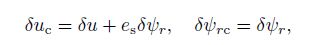 (10)
(10) where $u$ and $w$ are the displacement components of the plate mid-plane along the radial and thickness directions, respectively, and $\psi _r$ is the rotation of the middle surface (i.e., $z=0)$ of the plate in the $\theta $-direction.
Because of the axial symmetry in geometry and loading, the following displacement field is used based on the FSDT in the cylindrical coordinate system $(r, \theta , z)$:
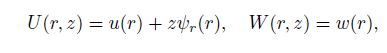 (11)
(11) where $U$ and $W$ are the displacements corresponding to the co-ordinate system, and they are functions of the spatial co-ordinates $u$, $w$, and $\psi _r$. Based on the nonlinear von-Karman strain-displacement relations, the following incremental strain terms compatible with the displacement field of Eq.(1) can be achieved[32]:
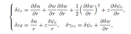 (12)
(12) where $\varepsilon _r $ and $\varepsilon _\theta $ are the normal strains along the $r$- and $\theta$-directions, respectively, and $\gamma _{rz} $ is the shear strain. Based on the linear constitutive elastic equations, the incremental form of the radial, circumferential, and transverse shear stresses $\sigma _r $, $\sigma _\theta $, and $\sigma _{rz} $ can be defined by
 (13)
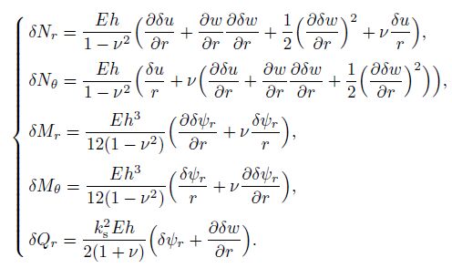
(13) The incremental stress and moment resultants ($\delta N_r $, $\delta N_\theta $, $\delta Q_r $, $\delta M_r $, and $\delta M_\theta )$ can be obtained by integrating the corresponding stresses along the thickness as follows:
 (14)
(14) where the shear correction factor $k_{\rm s}^2 =5/6$ is introduced to correct the discrepancy between the actual transverse shear force distributions and those computed by the kinematics relations of the FSDT. Substitute Eqs.(12) and (13) into Eq.(14). Then, we can obtain the incremental form of the constitutive relations in terms of the displacement field as follows:
 (15)
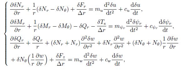
(15) As mentioned above, Fig. 2 shows the reaction body forces of the ring stiffener to the plate and the internal forces and moments acting on the cross section areas of the plate and stiffener. The large deflection stiffened plate equilibrium equations are derived by considering the equilibrium of the internal stress resultants and couples, the external pressure, and the interaction forces and couples between the plate and the stiffener acting on the small elements of the plate and stiffener. Here, for the interests of brevity, only the final forms of the equilibrium equations are presented[33], i.e.,
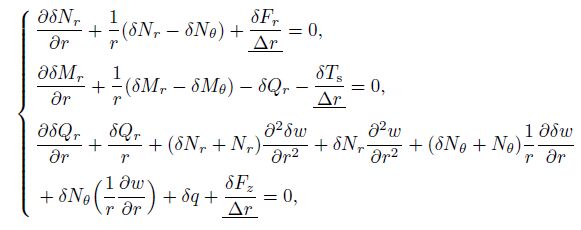 (16)
(16) where, with respect to the bending or buckling analysis, $\delta q$ can be a uniform transverse or radial in-plane compressive load. For the buckling analysis, $\delta q$ should be removed from the third relation of Eq.(16), and its effect will be applied in the boundary condition. Furthermore, $\Delta $ denotes an incremental radial coordinate. The underlined terms express the body force contributions of the ring stiffener to the plate equilibrium. It is clear that for the buckling analysis, $q$ should be eliminated from the third relation of Eq.(16). The displacement equilibrium equations can be obtained by the substitution of Eq.(15) into the force equilibrium equations appearing in Eq.(16), i.e.,
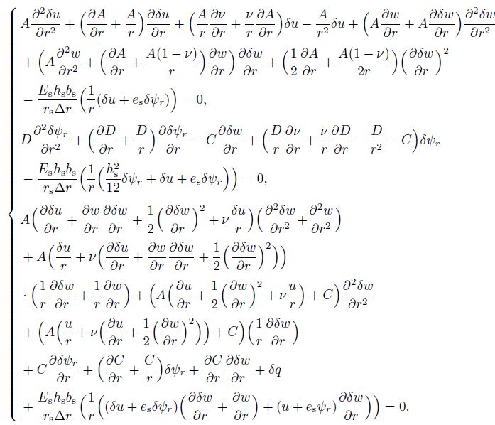 (17)
(17) It is noticed that the incremental load $\delta q$ is removed from the third relation of Eq.(17) for the buckling analysis.
3.2 Boundary conditionsIn order to complete the formulation of the problem, Eq.(17) should be accompanied by a set of boundary conditions. For a large deflection elastic circular plate analysis, there are many possible edge conditions that may be considered. In this study, only the in-plane-fixed/movable clamped and simply supported edge conditions are used for the bending analysis and the buckling analysis, respectively. The mentioned boundary conditions represent two extremes of the practical range of the edge conditions, and are set out below for both the bending analysis and the buckling analysis in terms of the constraints on the displacements, stress resultants, and stress couples around the circumference $r=r_{\rm o}$.
(i) For the bending analysis, the in-pane-fixed simply supported edge conditions are
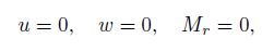 (18)
(18) and the in-plane-fixed clamped edge conditions are
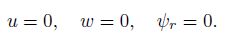 (19)
(19) (ii) For the buckling analysis, the in-plane-movable simply supported edge conditions are
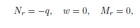 (20)
(20) and the in-plane-movable clamped edge conditions are
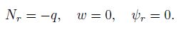 (21)
(21) Clearly, in the center of the solid circular plate ($r=0)$, the following boundary conditions should be used:
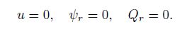 (22)
(22) Owing to the inherent intricacy of the stiffened plate, many sophisticated methods, such as the Rayleigh-Ritz method, the finite strip method, the finite element method, and the FD method[34-37], have been used for approximating the acceptable solution for these sorts of structures during the past decades. The set of nonlinear equilibrium equations are very complicated, and are not amenable to a closed form solution. Therefore, among the numerical solution methods, the DR method in conjunction with an FD discretization scheme is used in this study. The DR technique was first developed as a solution for the static analysis of linear elastic problems by Otter et al.[38] and Day[39]. In fact, the DR method is a step by step method for tracing the motion of a structure from the time of loading to when it reaches a steady state position owing to the effects of damping (for more details, see Refs.[40] and [41]). The DR method is a powerful and reliable technique for solving the highly nonlinear plate, dealing with bending and buckling problems. The formulation is explicit. This can make all quantities act as vectors. Therefore, less computer memory is allocated. Because of these benefits, the authors have decided to use the DR method, which many researchers have used to solve both linear and nonlinear problems[16-22, 42-43].
4.1 DR methodThe DR method is an explicit iterative procedure used to transfer a boundary value problem into a time-stepping initial value problem. This goal is achieved by adding the artificial inertia and damping forces to the right-hand side of Eq.(16). Then, the static system is transferred to the artificial dynamic system as follows:
 (23)
(23) where $m_u $, $m_{\psi _r}$, $m_{\rm w}$ and $c_u$, $c_{\psi _r } $, $c_{\rm w}$ are the elements of the diagonal fictitious mass and the damping matrices $M$ and $C$, respectively. The mentioned matrices must be selected in such a way to guarantee the stability and convergence of the iterative procedure. It is also noticed that a uniform transverse load is added to the left-hand side of the third relation of Eq.(23) for the bending analysis. There are some methods which have been used in evaluating the element values of the fictitious mass matrix $M$ (see Ref.[41]). Here, to guarantee the numerical stability, the elements of the diagonal matrix $M$ are determined by the Gershgörin theorem as follows (for more details, see Ref.[42]):
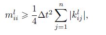 (24)
(24) where $l:(u, w, \psi _r)$, the superscript $n$ indicates the $n$th-iteration, and $\Delta t$ is the increment of the fictitious time. $k_{ij}$ is the element of the stiffness matrix $K$ calculated by
 (25)
(25) where $X$ ($X=u, \, w, \, \psi _r $) is the approximate solution vector, and $P$ is the left-hand side of Eq.(23). As mentioned above, a proper selection of $C$ can improve the convergence rate of the DR method. Five main approaches have been proposed in the published literature summarized in Ref.[41]. In this study, by applying the Rayleigh principle to each node, the instant critical damping factor for Node $i$ at the $n$th iteration is expressed by[41]
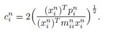 (26)
(26) Therefore, different values of $c$ for different nodes are introduced to obtain the form used for the DR method, i.e.,
 (27)
(27) A similar relation between $M$ and $m_{ii}^l $ is also used for the elements of the diagonal fictitious damping matrices $C$ and $c_{ii}^l $. In order to complete the DR procedure and transforming the formulae to the explicit nature, the acceleration and velocity terms at the time step $\Delta t$ of Eq.(23) must be replaced with the following approximate central FD expressions[42]:
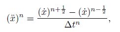 (28)
(28) 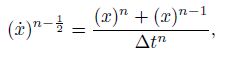 (29)
(29) 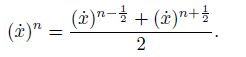 (30)
(30) Therefore, substituting the relations (28), (29), and (30) into the right-hand side of Eq.(23) yields the velocity equations as follows:
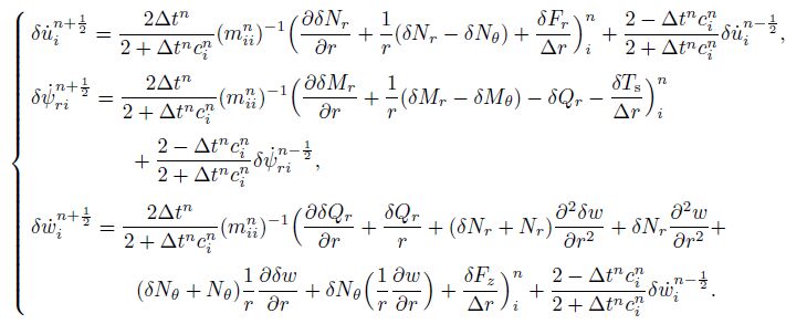 (31)
(31) At the end of each load step, the incremental displacements can be calculated by the following simple integration relation from Eq.(31):
 (32)
(32) Finally, in order to plot the stress-strain curve for finding the critical buckling load, the total displacements of each load must be computed. Therefore, the obtained incremental displacements computed by the DR method in each loadstep should be added to the displacements determined from the previous loadstep as follows:
 (33)
(33) Thus, in a specified load which is named as the critical buckling load, there is a large amount of displacement compared with the previous displacement in the obtained stress-strain curves. It is clear that, because of the axisymmetric nature of the loading and the plate geometry, only a radial line of the plate is used. Also, because of the singularity problem in the center, it is not possible to solve the equations in the central node of the plate. Therefore, the limiting process suggested by Kobayashi and Turvey[44] is employed here to overcome this problem. It is notable that the governing equations for the displacement field (see Eq.(17)) have very long terms. Thus, for the sake of briefness, Eq.(23) has been written based on the force equilibrium equation (see Eq.(16)). In our analysis, however, the developed numerical code is based on the displacement equations, which can be attained by replacing the left-hand side of Eq.(23) with the left-hand side of Eq.(17). Therefore, Eqs.(17) and (31)--(33) together with the appropriate boundary conditions in their FD forms constitute the set of equations for the sequential DR method. For the sake of brevity, the DR algorithm, which is clearly explained in Refs.[5] and [6], is omitted.
In order to clarify the procedure for the buckling analysis, it is noted that the external in-plane load is applied to the plate incrementally so that, in each loadstep, the incremental form of the governing equations can be solved by a numerical code prepared based on the DR method. After converging the DR code in the first increment, the latter loadstep is added to the previous one, and the program is repeated again. It should be said that at the end of the convergence in each loadstep, the obtained displacement is also added to those computed in the previous loadstep. This process continues till the code diverges, and this is a sign of buckling event. In other words, when the buckling occurs, a huge amount of displacement will be observed in the compressive load-displacement curve at a specified load. A comprehensive illustration is presented in Fig. 3 for predicting the critical buckling load based on the in-plane load-displacement curve. Also, as depicted in Fig. 3, the buckling load obtained by the DR solutions are compared with the classical results reported by Ref.[45] for the non-stiffened isotropic circular plate with the clamped in-plane movable edge condition, e.g., $E=70$~Gpa, $\nu =0.3$, $r_{\rm o}=100$~mm, and $h=10$~mm. From Fig. 3, we can see that the results obtained by the present method are in good agreement with those obtained by Ref.[45]. The little difference between the results is owing to the existing differences of the solution methodology and also the type of the used plate theory. It is notable that the numerical error produced in each loadstep is a kind of initial imperfections in the procedure. It should also be noticed that, with the presented incremental form of formulation, the bending analysis can also be conducted if the whole load is applied simultaneously.

|
| Fig. 3 Comparison between in-plane load-displacement curve obtained by DR solution and classical results reported by Ref.[45] for predicting ciritical buckling load of non-stiffened isotropic circular plates |
|
|
To examine the applicability of the proposed method and investigate its accuracy, the DR solutions are compared with the commercial finite element package of ABAQUS and also those available in the literatures for linear/nonlinear bending and buckling of isotropic/FGM plates with/without stiffeners. First, the numerical results obtained from the DR solutions are compared with the analytical results obtained by Reddy et al.[46] in Table 1 for the axisymmetric bending of a circular plate with simply supported and clamped boundary conditions. As indicated in Table 1, good agreement can be observed for the dimensionless maximum deflection $\overline {w}_{\max } =64w_{\max } D_{\rm c} /qr_{\rm o}^4 $, where $D_{\rm c} =E_{\rm c} h^3/12(1-\nu ^2)$.

|
For the second example, the DR large deflection results of the ring-stiffened isotropic circular plate with $b_{\rm s}/h_{\rm o} =1$, $h_{\rm s}/h=4$, and $r_{\rm s}/r_{\rm o}=0.5$ are compared with those reported by Turvey and Avanessian[20] in Fig. 4 for both clamped and simply supported boundary conditions. As illustrated in Fig. 4, the obtained results are in good consistency with those given in Ref.[20]. Owing to the lack of research for the nonlinear bending of the RFG circular plate, in the third sample, the DR solutions are compared with the results obtained by the ABAQUS finite element model. In Table 2, the obtained results of the two mentioned methods are presented for the maximum dimensionless deflection ($\overline{w}_{\max } =w_{\max } /h_{\rm o})$ of the clamped and simply supported RFG stiffened/unstiffened plate subjected to $\overline {q}=500$ with $h/r_{\rm o}=0.05$, $\xi =4$, and $r_{\rm s}/r_{\rm o}=0.5$.

|
| Fig. 4 Comparison between results obtained by Ref.[45] (CPT) and present study (FSDT) for clamped and simply supported boundary conditions of ring-stiffened isotropic circular plate |
|
|

|
The material properties selected for the ceramic and metallic phases of the RFG plate are
 (34)
(34) From Table 2, we can see that the DR solution and the finite element solution agree well with each other. In Table 3, the current solution for the dimensionless critical buckling load ($\overline {p}=pr_{\rm o}^2 /D$ and $D=Eh^3/12(1-\nu ^2))$ of the isotropic circular plate ($E=70$~GPa and $\nu =0.3)$ are compared with the results reported by Refs.[7] and [9] for different boundary conditions and thickness-to-radius ratios. The good consistency of the results denotes the high accuracy and precision of the applied method.

As the final case study, the results of the present method for the prediction of the critical buckling load $p_{\rm cr}$ (N$\cdot$mm$^{-1}$) of the RFG circular plate are compared with those obtained by the ABAQUS finite element software in Table 4 for different material grading indices, thickness-to-radius ratios, and boundary conditions. The material properties of this case are mentioned in Eq.(34).

|
As observed, based on these verifications, it is deduced that the obtained results can guarantee the reliability and the accuracy of the present method.
6 Parametric studyIn the present work, the effects of various boundary conditions, grading indices, thickness-to-radius ratios, stiffener's positions, and stiffener depths are considered on the displacements, stresses, and critical buckling loads of the RFG ring-stiffened circular plates subjected to the transverse/in-plane compressive loads. The results are presented in terms of the following dimensionless quantities:

which are the dimensionless deflection (vertical displacement), the radial displacement, the load, the radial stress resultant, the shear stress resultant, and the radial moment resultant, respectively. It is convenient to organize the geometric variables of the stiffened plate into dimensionless groups as the plate thickness-to-radius ratio $\mu =h/r_{\rm o}$ and the stiffener depth-plate thickness ratio $\xi =h_{\rm s}/h$. The mechanical properties of the considered RFG plate are given in Eq.(34). As mentioned above, the elastic characteristic of the isotropic stiffener is the same as the metallic phase of the RFG plate. In order to keep the computations required for the bending and buckling of the stiffened circular plate parameter study, only a limited set of values are used for the principal parameters. Thus, unless stated otherwise, the geometric parameters assumed in the following presented results are $\mu =0.1$, $\xi =4$, $r_{\rm s}/r_{\rm o}=0.5$, and $b_{\rm s}/h=1$.
Figures 5 and 6 illustrate the linear and nonlinear behaviors of the maximum dimensionless deflection ($\overline {w}_{\max } =w_{\max } /h)$ and the radial moment resultant ($\overline {M}_{r _{\max }} =M_{r _{\max }} r_{\rm o}^2 /E_{\rm m} h^4)$ in terms of the dimensionless transverse load ($\overline {q}=qr_{\rm o}^4 /E_{\rm m} h^4)$ for different grading indices n=1.0, 5.0 of the RFG ring-stiffened circular plate with the clamped and simply supported boundary conditions, respectively. As expected, with the increase in the transverse load, the differences between the linear and nonlinear results are increased for the clamped and simply supported boundary conditions. As indicated in Fig. 5(a), the differences between the linear and nonlinear analyses of $\overline {w}_{\max } $ of the clamped ring stiffened plate subjected to $\overline {q}=50$ are about 10.59% and 23.58% for n=1.0, 5.0, respectively. However, as shown in Fig. 5(a), these values are about 58.21% and 68.27% for the simply supported plate, respectively. Also, as depicted in Fig. 5(b), the differences between the computed $\overline {M}_{r _{\max }} $ of the linear and nonlinear behaviors of the clamped boundary condition in $\overline {q}=50$ are about 6.12% and 14.69% for n=1.0, 5.0, respectively. While for the simply supported case, these values are about 65.22% and 74.19%, respectively. Thus, as observed from Figs. 5 and 6, there are a huge amount of differences between the linear and nonlinear results for the clamped and especially simply supported boundary conditions. Hence, owing to the mentioned large discrepancy, considering the effects of the large deflections in the analyses is necessary and unavoidable for a precise prediction.

|
| Fig. 5 Maximum dimensionless deflection ($\overline {w}_{\max } )$ and maximum dimensionless radial moment resultant ($\overline {M}_{r_{\max }} )$ along radius for linear and nonlinear bending analyses of stiffened circular plate with clamped edge constraint, where $h/r_{\rm o}=0.1$, and $\xi =4$ |
|
|

|
| Fig. 6 Maximum dimensionless deflection ($\overline {w}_{\max } )$ and maximum dimensionless radial moment resultant ($\overline {M}_{r_{\max }} )$ along radius for linear and nonlinear bending analyses of stiffened circular plate with simply supported edge constraint, $h/r_{\rm o}=0.1$, and $\xi =4$ |
|
|
The variations of $\overline {w}$ and $\overline {u}$ along the radial directions of the stiffened and unstiffened circular RFG plates with $n=1.0$, 5.0 under a uniform loading ($\overline {q}=50)$ are depicted in Figs. 7 and 8 for the clamped and simply supported boundary conditions, respectively. As observed in Fig. 7(a), the effect of the stiffener is to cause reduction on the maximum deflection about 31.4% and 22.63% for {$n=1.0, $ 5.0}, respectively, in the clamped boundary condition, while the mentioned values are about 16.37% and 12.11% for $n=1.0, $ $5.0$, respectively, in the simply supported case (see Fig. 8(a)). Also, the stiffener reduces the maximum of $\overline {u}$ about 29.12% and 5.11% for {$n=1.0, $ 5.0, } respectively, in the clamped boundary condition, while the mentioned values are 4.22% and 7.28% in the simply supported boundary condition for $n=1.0, $ $5.0$, respectively. Thus, as depicted, the effect of the stiffener on the reduction of $\overline {w}$ and $\overline {u}$ is larger in the clamped boundary condition than in the simply supported boundary condition.

|
| Fig. 7 Dimensionless vertical displacement ($\overline {w})$ and dimensionless radial displacement ($\overline {u})$ along radius of clamped stiffened and unstiffened circular plates subjected to uniform transverse loading ($\overline {q}=50), $ where $h/{r_{\rm o}=0.1}$, and $\xi =4$ |
|
|

|
| Fig. 8 Dimensionless vertical displacement ($\overline {w})$ and dimensionless radial displacement ($\overline {u})$ along radius of simply supported stiffened and unstiffened circular plates subjected to uniform transverse loading ($\overline {q}=50)$, where $h/{r_{\rm o}=0.1}$, and $\xi =4$ |
|
|
Figure 9 demonstrates the effect of the stiffener on the dimensionless radial moment resultant $\overline {M}_r $ along the radial direction of the RFG circular plate subjected to $\overline {q}=50$ with {$n=1.0, $ 5.0} for the clamped and simply supported boundary conditions. As shown in the figure, owing to the presence of the stiffener, the radial moment resultant is discontinuous, and encounters a large ascending. This discontinuity is much greater in the simply supported boundary condition than in the clamped boundary condition.

|
| Fig. 9 Dimensionless radial moment resultant ($\overline {M}_r)$ along radius of stiffened and unstiffened circular plates with clamped and simply supported boundary conditions subjected to uniform loading ($\overline {q}=50)$, where $h /{r_{\rm o}=0.1}$, and $\xi =4$ |
|
|
Figure 10 shows the variations of the dimensionless stress resultant $\overline {N}_r $ in terms of the radial direction of stiffened and unstiffened RFG circular plates subjected to $\overline {q}=50$ with {$n=1.0, $ 5.0} for the clamped and simply supported boundary conditions, respectively. As it is illustrated, by applying the stiffener, the values of $\overline {N}_r $ of the stiffened case decrease more significantly than the unstiffened case. In the location of the stiffener, the variations of $\overline {N}_r $ are discontinuous, and encounter a large fall, unlike the behavior of $\overline {M}_r $. It is also notable that the mentioned reduction and discontinuity are much greater for the clamped boundary condition than for the simply supported boundary condition. The differences of $\overline {N}_{r\max }$ at the center of the plate between the stiffened and unstiffened conditions are about 43.73% and 30.08% for {$n=1.0, $ 5.0}, respectively, in the clamped boundary condition, whereas the mentioned values in the simply supported boundary condition are 13.46% and 11.11% for {$n=1.0, $ 5.0.}, respectively.

|
| Fig. 10 Dimensionless radial stress resultant ($\overline {N}_r)$ along radius of stiffened and unstiffened circular plates with clamped and simply supported boundary conditions subjected to uniform loading ($\overline {q}=50)$, where $h/r_{\rm o}=0.1, $ and $\xi=4$ |
|
|
Figure 11 demonstrates the effects of the stiffener on the dimensionless shear stress resultant $\overline {Q}_r $ along the radial direction of the RFG circular plate under $\overline {q}=50$ with $n=1.0, $ 5.0 for the clamped and simply supported boundary conditions. From the figure, we can see that when the stiffener is used, the value of $\overline {Q}_r $ increases. This event is more considerable in the simply supported case than in the clamped case. There is a sharp peak in the location of the stiffener. This behavior is more significant on the variations of $\overline {Q}_r $ in the simply supported case. Therefore, the maximum value of $\overline {Q}_r $ along the radial direction occurs in the stiffener location for the simply supported boundary condition.

|
| Fig. 11 Dimensionless shear stress resultant ($\overline {Q}_r)$ along radius of stiffened and unstiffened circular plates with clamped and simply supported boundary conditions subjected to uniform loading ($\overline {q}=50)$, where $h/r_{\rm o} =0.1$, and $\xi =4$ |
|
|
In Table 5, the effects of the stiffener depth on the maximum dimensionless deflection ($\overline {w}_{\max } =w_{\max } /h)$ and the maximum dimensionless radial moment resultant, i.e., $\overline {M}_{r _{\max }} =M_{r _{\max }} r_{\rm o}^2 /E_m h^4, $ are investigated for various material grading indices in the clamped and simply supported RFG plates under $\overline {q}=50$. Expectedly, increasing $\xi $ leads to the reduction of the maximum deflection in both the simply supported and the clamped boundary conditions. However, with the increase in $\xi $, the parameter $\overline {M}_{r _{\max }}$ is going to decrease in the clamped boundary condition and increase in the simply supported boundary condition. The reduction amount of the maximum deflection between the values of $\xi =1$ and $\xi =4$ is about 31.26% and 25.21% for $n=0.5, \, 2.0$, respectively, in the clamped boundary condition. In the simply supported boundary condition, an increase in the mentioned values occurs about 16.53% and 13.52% for $n=0.5, \, 2.0$, respectively. Besides, the previous difference for the parameter of $\overline {M}_{r _{\max }} $ is about 4.22% and 2.11% for $n=0.5, \, 2.0$, respectively, in the clamped boundary condition, whereas in the simply supported boundary condition, these values are 60.34% and 61.29%, respectively.

|
In the following, the results are specified for the buckling analysis of the ring stiffened circular RFG plate. In Table 6, the critical buckling load of the stiffened and unstiffened circular RFG plates with $\xi =4$, $r_{\rm s}/r_{\rm o}=0.5$, and different thickness-to-radius ratios $h/r_{\rm o} =0.05, \, 0.10$ is presented for various material grading indices in the clamped and simply supported boundary conditions. Obviously, the stiffener causes a considerable increase in the critical buckling load.

|
The differences of the predicted critical buckling load are equal in the cases of stiffened and unstiffened circular plates when $h/r_{\rm o}=0.05$ under both the simply supported and the clamped boundary conditions, which are about 58% for all the material grading indices. However, the mentioned value when $h/r_{\rm o}=0.10$ varies to 57% and 51% in the clamped boundary condition and the simply supported boundary condition, respectively.
The effects of the stiffener position on the maximum dimensionless deflection $\overline {w}_{\max } $ in the clamped and simply supported RFG plates under $\overline {q}=50$ with different material grading indices are indicated in Fig. 12. Observably, in the clamped boundary condition, with an increase in $r_{\rm s} /r_{\rm o}$ from $0.25$ to $0.50, $ the values of the maximum deflection reduce. With an increase in this ratio from $0.5$ to $0.75$, an increase in $\overline {w}_{\max }$ happens. This is because that when $r_{\rm s} /r_{\rm o}$ increases from 0.25 to 0.5 and 0.75, the values of $\overline {w}_{\max } $ decrease continuously.

|
| Fig. 12 Effects of stiffener location on maximum dimensionless deflection ($\overline {w}_{\max } )$ of RFG stiffened circular plate for clamped and simply supported edges, where $h/r_{\rm o}=0.1, ~\xi =4$, and $\overline {q}=50$ |
|
|
In Fig. 13, the effects of the stiffener depth on the critical buckling load is considered in the clamped and simply supported circular plates with various material grading indices, where $h/r_{\rm o} =0.05$, $r_{\rm s} /r_{\rm o} =0.5$, $b_{\rm s} /h_{\rm o} =1$. It is noted that the results are also presented by the developed ABAQUS finite element model for the sake of further verification. Expectedly, by increasing $\xi $, the critical buckling load increases in both the simply supported condition and the clamped boundary condition. The differences for the obtained critical buckling load, in the clamped boundary condition, between $\xi =1$ and $\xi =4$ are about 53.27% and 49.53% for $n=0.5$ and $n=2$, respectively. However, in the simply supported boundary condition, the mentioned difference are about 52.63% and 52.54%, respectively.

|
| Fig. 13 Effects of stiffener depth on critical buckling load $p_{{\rm cr}}$ (N$\cdot$mm$^{-1}$), of RFG stiffened circular plate for clamped and simply supported edges, where $h/r_{\rm o} =0.05$, and $r_{\rm s} /r_{\rm o} =0.5$ |
|
|
Figure 14 shows the effects of the stiffener position on the critical buckling load in both the simply supported condition and the clamped boundary condition of the circular RFG plate with various material grading indices obtained by the developed ABAQUS finite element model and the DR method, where $h/r_{\rm o} =0.05$, $r_{\rm s}/r_{\rm o}=0.5$, and $b_{\rm s}/h_{\rm o}=1$. As presented in the figure, in the clamped boundary condition, the critical buckling load encounters ascending from $r_{\rm s} /r_{\rm o} =0.25$ to $r_{\rm s}/r_{\rm o}=0.5$, and then the mentioned value descends from $r_{\rm s} /r_{\rm o} =0.5$ to $r_{\rm s} /r_{\rm o} =0.75$. These occurrences act differently in the simply supported boundary condition so that the trend of the critical buckling load can increase from $r_{\rm s} /r_{\rm o} =0.25$ to $r_{\rm s} /r_{\rm o} =0.5$ and $r_{\rm s} /r_{\rm o} =0.75$.

|
| Fig. 14 Effects of stiffener location on critical buckling load $p_{{\rm cr}}$ (N$\cdot$mm$^{-1}$) of RFG stiffened circular plate for clamped and simply supported boundary conditions, where $h/r_{\rm o} =0.05, $ and $\xi =4$ |
|
|
The main purpose of this study is to used the DR method combined with the discretization technique to analyze the buckling and large deflection RFG ring-stiffened circular plates subjected to uniform transverse/in-plane compressive loads. To achieve this goal, the nonlinear governing equations are obtained in the incremental form based on the first-order shear deformation plate theory and the von Karman relations for large deflection. The critical buckling load is predicted based on the load-displacement curve obtained by solving the incremental form of the nonlinear equilibrium equations. Based on the presented incremental form of formulation, the bending analysis can be conducted if the whole load is applied simultaneously. After verification of the present solutions, a detailed parametric study is carried out to investigate the effects of the grading index, the thickness-to-radius ratio, the stiffener depth, the stiffener position, and various boundary conditions on the bending and buckling behaviors in detail. Some general inferences are as follows:
(i) The effect of the stiffener on the results is much greater in the functionally gradient plate with higher material grading indices.
(ii) The effect of the stiffener on the reduction of the displacement is larger in the clamped boundary condition than in the simply supported boundary condition.
(iii) According to the presence of a stiffener, the radial moment resultant is discontinuous, and encounters a large ascending. This discontinuity is much greater in the simply supported boundary condition than in the clamped boundary condition.
(iv) By applying stiffeners, the values of the stress resultant decreases significantly compared with the unstiffened case. Therefore, in the location of the stiffener, the variations of the stress resultant are discontinuous, and encounter a large fall. Unlike the behavior of the moment resultant, the mentioned reduction and discontinuity are much greater for the clamped boundary condition than for the simply supported boundary condition.
(v) Expectedly, increasing the stiffener depth-to-plate thickness ratio leads to the reduction of the maximum dimensionless deflection under both the simply supported condition and the clamped boundary condition. However, with the increase in the ratio, the moment resultant is going to decrease in the clamped boundary condition while increase in the simply supported boundary condition.
(vi) The values of the stiffener depth ascending the critical buckling load are approximately identical for both the simply supported and the clamped boundary condition.
(vii) In the clamped boundary condition, by changing the stiffener location, the critical buckling load encounters ascending from $r_{\rm s}/r_{\rm o}=0.25$ to $r_{\rm s}/r_{\rm o}=0.5$, and then the mentioned value descends from $r_{\rm s}/r_{\rm o}=0.5$ to $r_{\rm s} /r_{\rm o} =0.75$. These occurrences act differently in the simply supported boundary condition so that the trend of the critical buckling load can increase from $r_{\rm s} /r_{\rm o} =0.25$ to $r_{\rm s} /r_{\rm o} =0.5$ and $r_{\rm s} /r_{\rm o} =0.75$.
| [1] | Turvey, G., J. and Salehi, & M Elasto-plastic large deflection response of pressure loaded circular plates stiffened by a single diametral stiffener. Thin-Walled Structures, 46, 991-1002 doi:10.1016/j.tws.2008.01.006 (2008) |
| [2] | Nosier, A., and Fallah, & F Non-linear analysis of functionally graded circular plates under asymmetric transverse loading. International Journal of Non-Linear Mechanics, 44, 928-942 doi:10.1016/j.ijnonlinmec.2009.07.001 (2009) |
| [3] | Najafizadeh, M., M. and Eslami, & M., R Buckling analysis of circular plates of functionally graded materials under uniform radial compression. International Journal of Mechanical Sciences, 4, 2479-2493 (2002) |
| [4] | Prakash, T, ., Singha, M., K., and, Ganapathi, & M Thermal postbuckling analysis of FGM skew plates. Engineering Structures, 30, 22-32 doi:10.1016/j.engstruct.2007.02.012 (2008) |
| [5] | Golmakani, M., E. and Kadkhodayan, & M Large deflection analysis of circular and annular FGM plates under thermo-mechanical loadings with temperature-dependent properties. Composites Part B:Engineering, 42, 614-625 doi:10.1016/j.compositesb.2011.02.018 (2011) |
| [6] | Golmakani, M., E. and Kadkhodayan, & M Nonlinear bending analysis of annular FGM plates using higher-order shear deformation plate theories. Computers and Structures, 93, 973-982 doi:10.1016/j.compstruct.2010.06.024 (2011) |
| [7] | M, a, L., S. and Wang, & T., J Relationship between axisymmetric bending and buckling solutions of FGM circular plates based on third-order plate theory and classicalplate theory. International Journal of Solids and Structures, 41, 85-101 doi:10.1016/j.ijsolstr.2003.09.008 (2004) |
| [8] | M, a, L., S. and Wang, & T., J Nonlinear bending and post-buckling of a functionally graded circular plate under mechanical and thermal loadings. International Journal of Solids and Structures, 40, 3311-3330 doi:10.1016/S0020-7683(03)00118-5 (2003) |
| [9] | Saidi, A., R., Rasouli, A, ., and, Sahraee, & S Axisymmetric bending and buckling analysis of thick functionally graded circular plates using unconstrained third-order shear deformation plate theory. Computers and Structures, 89, 110-119 doi:10.1016/j.compstruct.2008.07.003 (2009) |
| [10] | Bayat, M, ., Saleem, M, ., Sahari, B., B., Hamouda, A., M. S., and, Mahdi, & E Thermo elastic analysis of a functionally graded rotating disk with small and large deflections. Thin-Walled Structures, 45, 677-691 doi:10.1016/j.tws.2007.05.005 (2007) |
| [11] | Golmakani, & M., E Large deflection thermo elastic analysis of shear deformable functionally gradedvariable thickness rotating disk. Composites Part B:Engineering, 45, 1143-1155 doi:10.1016/j.compositesb.2012.08.012 (2013) |
| [12] | Bayat, M, ., Sahari, B., B., Saleem, M, ., A, li, A, ., and, Wong, & S., V Bending analysis of a functionally graded rotating disk based on the first order shear deformation theory. Applied Mathematical Modelling, 33, 4215-4230 doi:10.1016/j.apm.2009.03.001 (2009) |
| [13] | Mousavi, S., M. and Tahani, & M Analytical solution for bending of moderately thick radially functionally graded sector plates with general boundary conditions using multi-term extended Kantorovich method. Composites Part B:Engineering, 43, 1405-1416 (2011) |
| [14] | Hosseini-Hashemi, S., H, Akhavan, H, ., Rokni-Damavandi-Taher, H, ., Daemi, D, ., and, Alibeigloo, & A Differential quadrature analysis of functionally graded circular and annular sector plates on elastic foundation. Material Design, 31, 1871-1880 doi:10.1016/j.matdes.2009.10.060 (2010) |
| [15] | Hosseini-Hashemi, S., H., Rokni-Damavandi-Taher, H, ., and, Akhavan, & H Vibration analysis of radially FGM sectorial plates of variable thickness on elasticfoundations. Computers and Structures, 92, 1734-1743 doi:10.1016/j.compstruct.2009.12.016 (2010) |
| [16] | Sepahi, O, ., Forouzan, M., R., and, Malekzadeh, & P Thermal buckling and postbuckling analysis of functionally graded annular plates with temperature-dependent material properties. Material Design, 32, 4030-4041 doi:10.1016/j.matdes.2011.03.063 (2011) |
| [17] | Golmakani, M., E. and Alamatian, & J Large defection analysis of shear deformable radially functionally graded sector plates on two-parameter elastic foundations. European Journal of Mechanics, Series A, Solids, 42, 251-265 doi:10.1016/j.euromechsol.2013.06.006 (2013) |
| [18] | Turvey, G., J. and Salehi, & M Circular plates with one diametral stiffener an elastic large deflection analysis. Computers and Structures, 63, 775-783 doi:10.1016/S0045-7949(96)00077-6 (1997) |
| [19] | Turvey, & G., J Axisymmetric elastic large deflection behavior of stiffened composite plates. Computers and Structures, 6, 72-88 (1983) |
| [20] | Turvey, G., J. and Der Avanessian, & N., G. V Elastic large deflection analysis of ring-stiffened circular plates using graded finite differences. Proceedings of the NUMETA 85 Conference, Swansea, 875-884 (1985) |
| [21] | Turvey, G., J. and Der Avanessian, & N., G. V Axisymmetric elasto-plastic large deflection response of ring stiffened circular plates. International Journal of Mechanical Sciences, 31, 905-924 doi:10.1016/0020-7403(89)90032-5 (1989) |
| [22] | Golmakani, & M., E Nonlinear bending analysis of ring-stiffened functionally graded circular plates under mechanical and thermal loadings. International Journal of Mechanical Sciences, 79, 130-142 doi:10.1016/j.ijmecsci.2013.12.004 (2014) |
| [23] | Golmakani, M., E. and Mehrabian, & M Nonlinear bending analysis of ring-stiffened circular and annular general angle-ply laminated plates with various boundary conditions. Mechanics Research Communications, 59, 42-50 doi:10.1016/j.mechrescom.2014.04.007 (2014) |
| [24] | Sh, en, & H., S Nonlinear thermal bending response of FGM plates due to heat conduction. Composites Part B:Engineering, 38, 201-215 doi:10.1016/j.compositesb.2006.06.004 (2007) |
| [25] | Ya, ng, J., and Shen, & H., S Nonlinear bending analysis of shear deformable functionally graded plates subjected to thermo-mechanical loads under various boundary conditions. Composites Part B:Engineering, 34, 103-115 doi:10.1016/S1359-8368(02)00083-5 (2003) |
| [26] | Klusemann, B., and Svendsen, & B Homogenization methods for multi-phase elastic composites:comparisons and benchmarks. Technische Mechanik, 30, 374-386 (2010) |
| [27] | Prakash, T, ., Singha, M., K., and, Ganapathi, & M Thermal postbuckling analysis of FGM skew plates. Engineering Structures, 30, 22-32 doi:10.1016/j.engstruct.2007.02.012 (2008) |
| [28] | Mo, ri, T., and Tanaka, & K Average stress in matrix and average elastic energy of materials with misfitting inclusions. Acta Metallurgica, 21, 571-574 doi:10.1016/0001-6160(73)90064-3 (1973) |
| [29] | Asthana, R., and Singh, & M Evaluation of Pd-based brazes to join silicon nitride to copper-cladmolybdenum. Ceramics International, 35, 3511-3515 doi:10.1016/j.ceramint.2009.05.011 (2009) |
| [30] | H, e, P, ., Fe, ng, J., C., and, Xu, & W Microstructure and kinetics of induction brazing TiAl-based intermetallics to steel 35CrMo using AgCuTi filler metal. Materials Science and Engineering, 418, 53-60 doi:10.1016/j.msea.2005.11.003 (2006) |
| [31] | Walker, C., A. and Hodges, & V., C Comparing metal-ceramic brazing methods. Welding Journal, 87, 43-50 (2008) |
| [32] | Kadkhodayan, M, ., Zhang, L., C., and, Sowerby, & R Analysis of wrinkling and buckling of elastic plates by DXDR method. Computers and Structures, 65, 561-574 doi:10.1016/S0045-7949(96)00368-9 (1997) |
| [33] | Turvey, G., J. and Salehi, & M Elasto-plastic large deflection response of pressure loaded circular plates stiffened by a single diametral stiffener. Thin-Walled Structures, 46, 991-1002 doi:10.1016/j.tws.2008.01.006 (2008) |
| [34] | Ki, rk, & C., L Vibration of centrally placed stiffened rectangular plates. Journal of the Royal Aeronautical Society, 65, 695-697 doi:10.1017/S0368393100075544 (1961) |
| [35] | Loughlan, & J The buckling performance of composite stiffened panel structures subjected to combined in-plane compression and shear loading. Computers and Structures, 29, 197-212 doi:10.1016/0263-8223(94)90100-7 (1994) |
| [36] | Palani, G., S., Iy, er, N., R., and, Appa-Rao, & T., V. S. R An efficient finite element model for static and vibration analysis of eccentrically stiffened plates/shells. Computers and Structures, 43, 651-661 doi:10.1016/0045-7949(92)90506-U (1992) |
| [37] | W, ah, & T Vibration of stiffened plates. Aero Quarterly, 15, 285-298 doi:10.1017/S0001925900010891 (1964) |
| [38] | Otter, J., R. H., Cassell, A., C., and, Hobbs, & R., E Dynamic relaxation. Proceedings of the Institution of Civil Engineers, 35, 633-656 doi:10.1680/iicep.1966.8604 (1966) |
| [39] | D, ay, & A., S An introduction to dynamic relaxation. The Engineer, 219, 218-221 (1965) |
| [40] | Underwood, P. Dynamic Relaxation, in Computational Methods for Transient Analysis, Elsevier, Amsterdam (1983) |
| [41] | Zhang, L., C., Kadkhodayan, M, ., and, Mai, & Y., W Development of the maDR method. Computers and Structures, 52, 1-8 doi:10.1016/0045-7949(94)90249-6 (1994) |
| [42] | Zhang, L., C. and Yu, & T., X Modified adaptive dynamic relaxation method and application to elastic-plastic bending and wrinkling of circular plate. Computers and Structures, 33, 609-614 doi:10.1016/0045-7949(89)90035-7 (1989) |
| [43] | Golmakani, M., E. and Kadkhodayan, & M Large deflection thermoelastic analysis of functionally graded stiffened annular sector plates. International Journal of Mechanical Sciences, 69, 94-106 doi:10.1016/j.ijmecsci.2013.01.033 (2013) |
| [44] | Kobayashi, H., and Turvey, & G., J On the application of a limiting process to the dynamic relaxation analysis of circular membranes, circular plates and spherical shells. Computers and Structures, 48, 1107-1116 doi:10.1016/0045-7949(93)90443-H (1993) |
| [45] | Jawad, M. H. Theory and Design of Plate and Shell Structures, Chapman & Hall, New York (1994) |
| [46] | Reddy, J., N., Wa, ng, C., M., and, Kitipornchai, & S Axisymmetric bending of functionally graded circular and annular plates. European Journal of Mechanics, Series A, Solids, 18, 185-199 doi:10.1016/S0997-7538(99)80011-4 (1999) |