 2014, Vol. 35
The Chinese Meteorological Society
Article Information
- Xiao YANG, Zheng YANG, Qun WEN 2014.
- Bending of simply-supported circular timber beam strengthened with
- Appl. Math. Mech. -Engl. Ed., 35 (3) : 297–310
- http: //dx. doi. org/10.1007/s10483-014-1792-x
Article History
- Received 2012-11-12;
- in final form 2013-07-08


1 Introduction
Because of its renewability,processing facilities,good ductility,and elegant appearance, wood has been widely used in all types of building structures since ancient times. There are still many ancient wooden buildings in China,which have significant historical and cultural values. Meanwhile,due to environmental protection,low cost,and other factors,nearly half a century,a large number of new-type residential wooden structures,bridges,and long-span structures have been constructed in North America,Northern Europe,New Zealand,and other developed countries. Furthermore,as one of the architectural structures of sustainable development,the new type of light wooden structures is now also increasing in China. However,since the timber has the low elastic modulus,low strength,large creep,easy corrosion and aging,as well as various natural defects,wooden structures require rehabilitation and reinforcement regularly.
Since the 1990s,the theories and technologies of rehabilitation and reinforcement of the wooden structural members with a fiber reinforced polymer (FRP) have been focused,and the studies have shown that the rehabilitation and reinforcement of the wooden members with the FRP materials may increase their carrying capacity,reduce their deformation,and compensate for defects of the wooden members such as aging[1]. Currently,the glass fiber reinforced polymer[2, 3, 4] (GFRP),carbon fiber reinforced polymer[1, 5, 6] (CFRP),and aramid fiber reinforced polymer[7, 8] (AFRP) are mainly used to strengthen and rehabilitate the wooden members[9]. In the reinforcement of the timber beams for bending resistant,the FRP is usually glued or embedded on the tension surface of the timber beam[1, 2, 4, 6, 7, 8, 10, 11],while for shear resistant,the FRP is usually pasted on the lateral sides or embedded in the timber beam[2, 3, 12, 13, 14]. However,these studies are mainly focused on the feasibility and effectiveness of the timber beams strengthened with the FRP by the experimental investigations[1, 6, 7, 12] and the numerical simulations of finite element methods[6, 8, 11, 14]. Furthermore,the main interests are focused on the carrying capacity,failure modes,and ductility of the FRP-strengthened timber beams with rectangular cross-section. Nevertheless,to the best of the authors’ knowledge,there is no research on the bending behavior of the FRP-strengthened timber beam with circular crosssection. There are a lot of timber beams with circular cross-section in many ancient wooden structures and new constructions in China. Thus,the studies on the bending performances of the FRP-strengthened circular timber beams have important theoretical significance and direct application backgrounds.
The bending of the simply-supported circular timber beam strengthened with a CFRP sheet is investigated in this paper,and the influence of the CFRP-reinforcement layer on the bending performances of the timber beam is analyzed. Firstly,with the plane section hypothesis of the beam bending,considering the nonlinear stress-strain relation of the timber,the influence of the sectional stress distribution on the tensile strength of the timber,and the characteristic of the resisting tension and no-resisting compression of the FRP-reinforcement layer,the position of the neutral axis of the circular timber beam strengthened with the CFRP sheet is determined, and the analytical expression for the bending moment-curvature relation is presented. Then, the nonlinear boundary value problem for the small deflection bending of the simply-supported circular timber beam strengthened with the CFRP sheet subject to a uniform load is established,and its bending performances are obtained numerically. The influence of the angle and thickness of the CFRP-reinforcement layer on the deflection of the strengthened circular timber beam is examined. At the same time,the nonlinear bending moment-curvature relation of the CFRP-strengthened circular timber beam is approximated as a bilinear constitutive model. The approximate deflection-load curves of the simply-supported CFRP-strengthened circular timber beam are obtained,and the approximation degree of the bilinear constitutive model is analyzed.
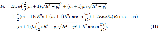
2 Bending moment-curvature relation of circular timber beam strengthened with CFRP sheetAs shown in Fig. 1,an FRP sheet with the modulus EF and the ultimate tensile failure strain εFRP is glued on the tensional surface of the circular cross-section timber beam with the radius R and the cross sectional area AW. The FRP sheet has the thickness t (t << R),the central angle 2α,and the area AF. Furthermore,it is assumed that the reinforcement layer of the FRP sheet has a characteristic of the resisting tension and no-resisting compression. The stress-strain relation of the timber for tension can be approximated as a straight line,while its stress-strain relation for compression is approximated as a bilinear line,in which its strength depends on the sectional stress distribution[15, 16]. Figure 2 shows the stress-strain relation of the timber for the unidirectional tension and compression with the tensile modulus EW,the ultimate failure tensile strain εm,and the ultimate tensile failure stress fm. The timber yield occurs when the compression strain equals the yield strain εc with the yield stress fc. After yielding,the stress-stain relation of the timber is still a straight line with the slope −mEW, where m is a constant. Considering the influence of the sectional stress distribution on the tensile strength of the timber,the ultimate tensile stress ft of the timber for bending can be expressed as[16]
where e is the Oy-axis coordinate of the neutral axis of the cross-section (see Fig. 1),and k is a parameter of the cross-sectional height,reflecting the effect of the sectional height on the timber strength[16].
 |
| Fig. 1. Geometric parameters of FRP-strengthened circular cross-section timber beam. |
 |
| Fig. 2. Uniaxial stress-strain relation of timber. |
For the small deflection bending of the circular cross-section timber beam strengthened with an FRP sheet,it is assumed that the bending of the timber beam satisfies the plane section hypothesis,and the FRP-reinforcement layer only undergoes the uniform axial tension and compression,which are constant along its thickness. Furthermore,it is assumed that the FRPreinforcement layer is bonded tightly with the beam surfaces,and there is no separation and slip between them.
Therefore,the axial stresses σw and σF of the timber beam and the FRP-reinforcement layer can be expressed,respectively,as
where εt = ft/EW,and εw and εF are the axial strains of the timber beam and the FRPreinforcement layer,respectively. Denote the bending curvature of the circular timber beam strengthened with the FRP sheet to be φ. Then,it has

in which (r,θ) is the polar coordinates of the beam cross-section.
Bending failure of the circular timber beam strengthened with the FRP sheet can be divided into the following states: (i) Both the timber and the FRP-reinforcement layer are linearly elastic,and the tensile fracture failure occurs to the timber fiber. (ii) Both the timber and the FRP-reinforcement layer are linearly elastic,and the tensile fracture failure occurs to the fiber of the FRP-reinforcement layer. (iii) The compression region of the timber beam has yielded, while the FRP-reinforcement layer is linearly elastic,and the tensile fracture failure occurs to the timber fiber. (iv) The compression region of the timber beam has yielded,while the FRPreinforcement layer is linearly elastic,and the tensile fracture failure occurs to the fiber of the FRP-reinforcement layer.
(i) When both the timber and the FRP-reinforcement layer are linearly elastic,and the tensile fracture failure occurs to the timber fiber,it requires that εt < εFRP,and (R + e)εt/(R − e) < εc. In such a case,if the FRP-reinforcement layer is located in the tensile side of the timber beam,then the axial force on the cross-section of the FRP-strengthened circular timber beam is

Since there is no axial force of the FRP-strengthened timber beam,i.e.,FN= 0,the neutral axis position for the linearly elastic bending of the FRP-strengthened circular timber beam is
If the central angle of the FRP-reinforcement layer is large enough so that there is the FRP-reinforcement layer in the compression region of the timber beam,i.e.,the neutral axis intersects with the FRP-reinforcement layer. Because of the characteristic of the resisting tension and no-resisting compression of the FRP-reinforcement layer,the FRP-reinforcement layer in the compression region cannot undertake the stress,and the effective angle α0 of the FRP-reinforcement layer satisfies

Let α = α0 in the expression (6). With the expression (7),it can be obtained that

The central angle α0 is determined with the above expression,and the neutral axis position e0 can be determined with the expression (7).
After the neutral axis position e0 is determined,the bending moment of the normal stress on the cross-section of the FRP-strengthened circular timber beam can be expressed as

where IF = Rt((R2 + 2e20)α + R(R cos α − 4e0) sin α),and IW = IW + πR2e20,in which IW0 = πR4/4 is the cross-sectional inertia moment of the unreinforced circular timber beam,and (EI)eq is the equivalent flexural rigidity of the FRP-strengthened circular timber beam.
(ii) When both the timber and the FRP-reinforcement layer are linearly elastic,and the tensile fracture failure occurs to the fiber of the FRP-reinforcement layer,it requires that εt > εFRP,and (R + e)εt/(R − e) < εc. Before the fracture failure occurs,the bending moment on the cross-section of the FRP-strengthened circular timber beam can still be given by the expression (9).
(iii) When the compression region of the timber beam has yielded,while the FRP-reinforcement layer is linearly elastic,and the tensile fracture failure occurs to the timber fiber, it requires that εt < εFRP,and (R + e)εt/(R − e) > εc. In such a case,the linearly elastic bending occurs to the FRP-strengthened circular timber beam firstly,and the bending moment can be determined with the expression (9). When the bending curvature φ is increased to (R + e0)φ = εc,the compression region of the FRP-strengthened circular timber beam begins to yield. The neutral axis position changes,and the distributions of the axial strains and stresses on the cross-section are shown in Fig. 3. With the geometrical relations,it can be obtained that

 |
| Fig. 3. Distributions of strain and stress on cross-section of FRP-strengthened circular timber beam when compression region yields. |
The axial force on the cross-section of the FRP-strengthened circular timber beam can be expressed as
From the condition FN= 0,the neutral axis position can be expressed as

If the neutral axis intersects with the FRP-reinforcement layer,then the effective central angle α of the FRP-reinforcement layer is determined with FN= 0 and e = R cos α. That is,it has

After the neutral axis position is determined,the bending moment of the normal stress on the cross-section of the FRP-strengthened circular timber beam is

At this time,to ensure the stress on the yield region of the cross-section to be compressive, it requires that
(iv) When the compression region of the timber beam has yielded,while the FRP-reinforcement layer is linearly elastic,and the tensile fracture failure occurs to the fiber of the FRPreinforcement layer,it requires that εt > εFRP,and (R + e)εt/(R − e) > εc. In such a case,the linearly elastic bending occurs to the FRP-strengthened circular timber beam firstly,and the bending moment can still be determined with the expression (9). When the bending curvature φ is increased to (R + e0)φ = εc,the compression region of the FRP-strengthened circular timber beam begins to yield,and the bending moment can be determined with the expression (14) under the condition (15). 3 Bending of simply-supported circular timber beam strengthened with CFRP sheet 3.1 Boundary value problem of nonlinear model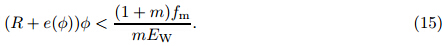
Consider a simply-supported circular timber beam strengthened with an FRP sheet with the length L subject to a uniform load Q (see Fig. 4),and denote the deflection of the FRPstrengthened timber beam to be w(x) and the bending moment and shear force on the crosssection to be M(x) and FS(x),respectively. Then,the equilibrium equations of the FRPstrengthened timber beam are

 |
| Fig. 4. Simply-supported circular timber beam strengthened with FRP sheet subject to uniform transversal load. |
For the small deflection bending,the bending moment-curvature relation discussed above can also be expressed as

The corresponding boundary conditions can be expressed as

To solve the nonlinear boundary value problem of (16)-(18),denote

Then,the boundary value problem (16)-(18) can be transformed to the following boundary value problem of first-order nonlinear differential aligns:


where Y = (y1,y2,y3,y4)T,and F(Y) = (y2,−g(y4),Q,y3)T.
The above boundary value problem of nonlinear differential aligns can be solved numerically with the modified Runge-Kutta method[17, 18]. If the simply-supported circular timber beam strengthened with the FRP sheet is in the linearly elastic bending stage,i.e.,φ = M/(EI)eq, then the deflection is
3.2 Approximate deflection of bilinear constitutive model
Rasheed et al.[19] simplified the bending moment-curvature relation of the reinforced concrete beam strengthened with the FRP sheet as a bilinear constitutive model,and an approximate method was presented for computing the bending deformation of the reinforced concrete beam strengthened with the FRP sheet. Here,Rasheed’s approximate bilinear model is generalized to the analysis of the elastoplastic bending of the FRP-strengthened circular timber beam. Denote the bending moment and curvature for the compression region starting to yield to be Mc and φc,respectively,and the ultimate bending moment and corresponding curvature on the crosssection to be Mu and φu,respectively. Then,from Fig. 5,the approximate bilinear bending moment-curvature relation of the FRP-strengthened circular timber beam can be expressed as follows:

 |
| Fig. 5. Bilinear moment-curvature relation of FRP-strengthened timber beam |
When the maximum bending moment of the FRP-strengthened circular timber beam subject to a uniform load Q satisfies Mmax = QL2/8 > Mc,there exist the elastic and plastic regions of the strengthened timber beam. It is not difficult to obtain that,for the bending of the timber beam,the distance between the boundary of the elastic region and the beam left end is

Therefore,the mid-span deflection wmax = w(L/2) of the simply-supported circular timber beam strengthened with the FRP sheet is[19]

where φ1(x) and φ2(x) are the curvatures of the elastic and plastic regions of the timber beam, respectively.
For the uniform load Q,it is easy to obtain that
4 Numerical results and analysis

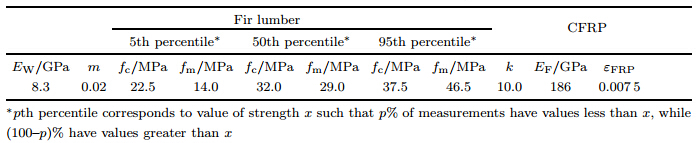
Now the reinforcement effect of the carbon fiber reinforced polymer (CFRP) on the bending deformation of the simply-supported circular fir beam is analyzed. Taking the material parameters as listed in Table 1[16, 20],Fig. 6 shows the variations of the dimensionless bending moment Mnor = MR/(EWIW0) versus the dimensionless curvature Φ = Rφ of the CFRP-strengthened timber beam with different strengths (different percentiles) for the reinforcement angle α = 30o and 60o and the relative reinforcement thickness t/R = 0.04 and 0.08. It can be seen that,with the increases of the reinforcement angle α and the thickness t/R,the ultimate bearing capacity and dimensionless flexural rigidity Ke = dMnor/dΦ of the FRP-strengthened timber beam are increased,and the ductility is enhanced. Furthermore,for the high strength timber beam (95th percentile) with the reinforcement angle α = 30o and 60o,the curves of the bending momentcurvature are almost the same when the curvature Φ becomes larger. It demonstrates that,with the compression region of the timber beam beginning to yield,the CFRP-reinforcement layer intersects with the neutral axis,and the neutral axes of the two cross-sections coincide. At this time,increasing the reinforcement angle will not increase the performances of the strengthened timber beam. In fact,it is found that,from the numerical results,the tensile fracture of the fir fiber occurs to the reinforcement fir beam with the low strength (5th and 50th percentiles), while the reinforcement fir beam with the high strength (95th percentiles) occurs to the tensile fracture of the CFRP fiber.
 |
| Fig. 6. Relation between dimensionless moment and dimensionless curvature of CFRP-strengthened timber beam with circular cross-section. |
Figure 7 shows the responses of the dimensionless mid-span deflection W0 = w(L/2)/L of the numerical solution of the nonlinear boundary value problem (20) and (21) versus the dimensionless load q = QL2R/(EWIW0) of the simply-supported circular timber beam strengthened with the CFRP sheet with the length-radius ratio L/R = 30 and the material parameters taking from the Table 1,and the dimensionless mid-span deflection of the analytical solution (22) for the linearly elastic bending is also given. It can be seen that the mid-span deflection W0 of the numerical solution of the nonlinear boundary value problem (20) and (21) is in good agreement with that of the analytical solution (22) in the linearly elastic stage. The reliability of the numerical solution of the nonlinear boundary value problem (20) and (21) is verified in some sense. With the increasing dimensionless load q,the CFRP-strengthened circular timber comes into the elastoplastic deformation stage,in which its mid-span deflection is larger than that of the linearly elastic bending. Furthermore,with the increasing reinforcement angle α and thickness t/R,the mid-span deflection W0 of the CFRP-strengthened circular timber beam decreases. However,when the reinforcement angle α > 60o,the reinforcement angle α has nearly no influence on the mid-span deflection W0 . At this time,the CFRP-reinforcement layer intersects with the neutral axis of the CFRP-strengthened circular timber beam.
 |
| Fig. 7. Mid-span deflection W0 of simply-supported circular timber beam strengthen with CFRP sheet subject to uniform load q. |
The distributions of the dimensionless deflections W(ξ) = w(x)/L along the dimensionless axial line ξ = x/L for the nonlinear bending (20)-(21) and the linearly elastic bending (22) of the simply-supported circular timber beam strengthened with the CFRP sheet with the lengthradius ratio L/R = 30,the relative reinforcement thickness t/R = 0.04,and the reinforcement angles α = 30o and 60o,respectively,are shown in Fig. 8. It can be seen that the solution of the nonlinear boundary value problem (20)-(21) coincides well with that of the linearly elastic bending (22) when the dimensionless load q is smaller,and the linearly elastic bending model can be used for analysis. With the increasing load q,the compression region of the timber beam occurs the plastic deformation,the solution of the nonlinear boundary value problem (20)-(21) is larger than that of the linearly elastic bending (22),and the difference between them increases with the increasing load q. When the dimensionless load q = 0.1,the deflection difference between the nonlinear and linearly bending is about 20% for the simply-supported CFRP-strengthened circular timber beam with high strength (95th percentile).
 |
| Fig. 8. Deflection distributions W(ξ) of simply-supported circular timber beam strengthened with CFRP sheet. |
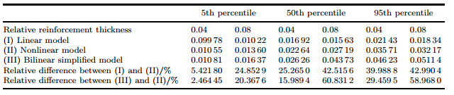
Figure 9 shows the comparisons of the mid-span dimensionless deflection W0 versus the dimensionless load q for the approximate bilinear bending moment-curvature constitutive model (23),the nonlinear bending moment-curvature constitutive model (17),and the linear constitutive model φ = M/(EI)eq of the simply-supported circular timber beam strengthened with the CFRP sheet. It is revealed that the mid-span deflection of the approximate bilinear model is larger than that of the nonlinear model. The reason is that the secant is employed in the bending moment-curvature relation of the approximate bilinear model to substitute the real curve of the bending moment-curvature relation which is convex. Consequently,the flexural rigidity of the approximate bilinear model is smaller than the real one of the strengthened timber beam,which results in the deflection increasing. Therefore,the stiffness analysis based on the approximate bilinear bending moment-curvature constitutive model is on the safe side. Furthermore,it is found that the values of the ultimate mid-span deflections of the nonlinear model can be approximated as the average values of the deflection of the linearly elastic and approximate bilinear models. Table 2 shows the comparisons of the ultimate mid-span deflection of the simply-supported CFRP-strengthened circular timber beam with different strengths for the linearly elastic,approximate bilinear,and nonlinear models when the reinforcement angle α = 60o,and the relative reinforcement thickness t/R = 0.04 and 0.08,respectively. It can be seen that the maximum relative difference of the mid-span deflection between the approximate bilinear and nonlinear models can be up to 50%. Therefore,the application of the approximate bilinear model has some limitations.
 |
| Fig. 9. Comparisons of ultimate mid-span deflection of simply-supported circular timber beam strengthened with CFRP sheet subject to uniform load q for different models. |
 |
By the nonlinear constitutive relation of the timber and the characteristic of the resisting tension and no-resisting compression of the FRP-reinforcement layer,the analytical expression for the bending moment-curvature relation of the circular timber beam strengthened with the FRP sheet is presented,and the bending performance of the simply-supported circular timber beam strengthened with the CFRP sheet is investigated. The effects of the timber strength,the thickness,and the angle of the reinforcement layer on the bending deformation of the circular timber beam strengthened with the CFRP sheet are examined,and the following conclusions can be obtained.
(i) Because of the characteristic of the resisting tension and no-resisting compression of the FRP-reinforcement layer,the FRP-reinforcement layer would be on the tensile region of the circular timber beam to give full play to the performance of the FRP materials. When the compressive region of the timber beam comes into the plastic state,the neutral axis position of the FRP-strengthened timber beam changes with the curvature. Therefore,the reinforcement angle α of the FRP sheet is an important factor,and the increase of the reinforcement angle does not necessarily improve the reinforcement effect.
(ii) Generally,the increases of the angle and thickness of the reinforcement layer can significantly improve the ultimate bearing capacity,the flexural rigidity,and the ductility of the
strengthened timber beam,and the effect of the thickness increase is superior to that of the angle increase. The failure mode of the strengthened timber beam can also be changed,and, in fact,the failure mode can be transformed from the brittle failure into the ductile one.(iii) When the load is smaller,the deflection of the nonlinear boundary value is in good agreement with that of the linearly elastic analytical solution,which verifies the reliability of the numerical method of the nonlinear boundary value problem. With the increasing load, the CFRP-strengthened circular timber comes into the elastoplastic deformation stage,and its deflection is larger than that of the analytical solution of the linearly elastic bending. The difference between them is increased as the load increases. For the circular timber beam with high strength,its relative difference can be up to 20%.
(iv) The deflection of the approximate bilinear mode is larger than that of the nonlinear model for the CFRP-strengthened circular timber beam,and the relative difference can exceed 50%. The deflection of the nonlinear model is between those of the linear and approximated bilinear models,and the values of the ultimate mid-span deflection of the nonlinear model can be approximated as the average values of the deflection of the linearly elastic and approximate bilinear models.
| [1] | Borri, A., Corradi, M., and Grazini, A. A method for flexural reinforcement of old wood beams with CFRP materials. Composites Part B: Engineering, 36(2), 143–153 (2005) |
| [2] | Triantafillou, T. C. Composites: a new possibility for the shear strengthening of concrete, masonry and wood. Composites Science and Technology, 58(8), 1285–1295 (1988) |
| [3] | Radford, D. W., Goethem, D. V., Gutkowski, R. M., and Peterson, M. L. Composites repair of timber structures. Construction and Building Materials, 16(7), 417–425 (2002) |
| [4] | Alhayek, H. and Svecova, D. Flexural stiffness and strength of GFRP-reinforced timber beams.Journal of Composites for Construction, 16(3), 245–252 (2012) |
| [5] | Lorenzis, L., Scialpi, V., and Tegola, A. Analytical and experimental study on bonded-in CFRP bars in glulam timber. Composites Part B: Engineering, 36(4), 279–289 (2005) |
| [6] | De Jesus, A. M. P., Pinto, J. M. T., and Morais, J. J. L. Analysis of solid wood beams strengthened with CFRP laminates of distinct lengths. Construction and Building Materials, 35(1), 817–8282012) |
| [7] | Qing, C. and Jian, W. P. Experimental study on bending behavior of timber beams reinforced with CFRP/AFRP hybrid FRP sheets. Advanced Materials Research, 255-260, 728–732 (2011) |
| [8] | Yahyaei-Moayyed, M. and Taheri, F. Experimental and computational investigations into creep response of AFRP reinforced timber beams. Composite Structures, 93(2), 616–628 (2011) |
| [9] | Zhuang, R. Z. and Yang, Y. X. Research and application on FRP in the reinforcement of timber structures (in Chinese). Sichuan Building Science, 34(5), 89–92 (2008) |
| [10] | Yang, H. F., Liu, W. Q., Shao, J. S., and Zhou, Z. H. Study on flexural behavior of timber beams strengthened with FRP (in Chinese). Journal of Building Materials, 11(5), 591–597 (2008) |
| [11] | Valipour, H. R. and Crews, K. Efficient finite element modelling of timber beams strengthened with bonded fibre reinforced polymers. Construction and Building Materials, 25(8), 3291–3300(2011) |
| [12] | Triantafillou, T. Shear reinforcement of wood using FRP materials. Materials in Civil Engineering,9(2), 65–69 (1997) |
| [13] | Akbiyik, A., Lamanna, A. J., and Hale, W. M. Feasibility investigation of the shear repair of timber stringers with horizontal splits. Construction and Building Materials, 21(5), 991–1000(2007) |
| [14] | Manalo, A. C., Aravinthan, T., Karunasena, W., and Islam, M. M. Flexural behaviour of structural fibre composite sandwich beams in flatwise and edgewise positions. Composite Structures, 92(4),984–995 (2010) |
| [15] | Buchanan, A. H. Combined bending and axial loading in lumber. Journal of Structural Engineering, ASCE, 112(12), 2592–2609 (1986) |
| [16] | Buchanan, A. H. Bending strength of lumber. Journal of Structural Engineering, ASCE, 116(5),1213–1229 (1990) |
| [17] | Shampine, L. F., Kierzenka, J., and Reichelt, M. W. Solving boundary value problems for ordinary differential equations in Matlab with bvp4c. Tutorial Notes (2000)(http://www.mathworks.com/bvp tutorial) |
| [18] | Kierzenka, J. and Shampine, L. F. A BVP solver based on residual control and the Maltab PSE.ACM Transactions on Mathematical Software (TOMS), 27(3), 299–316 (2001) |
| [19] | Rasheed, H. A., Charkas, H., and Melhem, H. Simplified nonlinear analysis of strengthened concrete beams based on a rigorous approach. Journal of Structural Engineering, 130(7), 1087–1096(2004) |
| [20] | Plevris, N. and Triantafillou, T. FRP-reinforced wood as structural material. Journal of Materialsin Civil Engineering, ASCE, 4(3), 300–317 (1992) |