 2018, Vol. 39
Shanghai University
Article Information
- Xudong ZHENG, Runsen ZHANG, Qi WANG
- Comparison and analysis of two Coulomb friction models on the dynamic behavior of slider-crank mechanism with a revolute clearance joint
- Applied Mathematics and Mechanics (English Edition), 2018, 39(9): 1239-1258.
- http://dx.doi.org/10.1007/s10483-018-2371-9
Article History
- Received Mar. 18, 2018
- Revised Apr. 16, 2018


Because of manufacturing tolerance, wear, plastic deformation, and so on, practical joints in multibody mechanical systems always include clearances. Clearances may lead to friction and impact between the components of joints, which have significant influence on the dynamic responses of the systems.
In recent years, a great number of researchers have studied problems of modeling and analyzing multibody systems including clearance joints[1-7]. Erkaya and Uzmay[8] and Erkaya and Doǧan[9] studied kinematic and dynamic characteristics of planar multibody systems with link flexibility and joint clearance. They also carried out both experimental and numerical investigations to analyze the effects of joint clearance on conventional articulated and partly compliant mechanisms[10-11]. Flores and his research group have valuable contributions about joint clearance in thematic literature. Dry contact including friction and lubrication effects between bearing and journal parts[12-15], and different joint types and clearance sizes in two-dimensional and three-dimensional mechanism motions[16-19] were investigated by them. Rahmanian and Ghazavi[20] and Farahan et al.[21-22] studied nonlinear dynamic behaviors and bifurcation in multibody systems with revolute clearance joints. Bai et al.[23-24] and Bai and Sun[25] investigated the effects of different normal contact force models and body flexibility on dynamic characteristics of mechanical systems with clearance joints. They also presented the wear prediction for revolute clearance joint in multibody systems using the Archard' s wear model[26-27]. Qi et al.[28] and Wang et al.[29] proposed recursive formulations for multibody systems including frictional joints with tiny clearances using the interactions between bodies, and presented a constraint-based approach for modeling revolute clearance joints of planar multi-rigid-body systems. Based on the absolute nodal coordinate formulation (ANCF), Tian et al.[30-32] and Wang et al.[33] investigated planar/spatial flexible multibody systems with dry and lubricated clearance joints. Yan and Guo[34] and Xiang et al.[35] presented a general method of kinematic accuracy analysis for the flexible planar mechanisms with uncertain link lengths and joint clearances, and discussed the coupled iterative analyses between system dynamic response and joint wear prediction. However, all these studies mentioned above were based on the modified Coulomb friction model. Although it can avoid numerical difficulties when the relative tangential velocity is in the vicinity of zero, the modified Coulomb friction model does not produce any force at zero relative velocity, and exhibits poor capability to simulate stiction and stick-slip motion[36-37].
Different from the aforementioned studies, some researchers investigated multibody systems with clearance joints using the LuGre friction model. Muvengei et al.[38-39] studied the dynamic behaviors of planar multibody systems with LuGre friction at different located revolute clearance joints, and found that the effect of stick-slip friction on the overall dynamic behavior at different speeds varies from one clearance joint to another. Zhao et al.[40] presented a method for modeling and analyzing planar multibody systems with mixed lubricated revolute joints based on the finite element method and the Lagrange equations. Zheng and Zhou[41] and Zheng et al.[42] investigated the dynamics of flexible multibody systems including joints with clearance and lubrication for press systems via the software ADAMS. However, the LuGre friction model introduces extra degree of freedom (DOF), and requires the determination of a large number of parameters, which can hardly be gained even by experiments in most cases. Therefore, it cannot be adopted easily[36-37].
The purpose of this paper is to compare and analyze the influence of using the Coulomb dry friction model and the modified Coulomb friction model on the dynamic response of the slider-crank mechanism with a revolute clearance joint. The advantages of the Coulomb dry friction model include that it can capture stiction and stick-slip motion and requires a small number of selected parameters. The main difficulty in solving contact problems with dry friction results from instantaneous changes of the frictional forces at transitions from sliding to sticking or reversed sliding. Fortunately, these problems can be solved by the linear complementarity problem (LCP) algorithm[43-46] or trial-and-error algorithm[47]. The trial-and-error algorithm can be employed expediently when there is only one pair of contact points. However, the LCP algorithm is much more efficient dealing with multipoint contact problems with friction[48], and the results can be tested by the trail-and-error algorithm. Flores et al.[49] proposed an LCP algorithm for dynamic modeling and analysis of rigid multibody systems with translational clearance joints. Zhuang and Wang[50-51] and Wang et al.[52] presented a constraint-stabilized method for the planar multi-rigid-body system possessing translational joints with tiny clearances and friction based on the horizontal linear complementarity problem (HLCP) algorithm. Krinner and Thümmel[53] investigated a planar 6-bar linkage mechanism with revolute clearance joints using the methods of unilateral contacts. Akhadkar et al.[54-55] used nonsmooth contact dynamics (NSCD) approach to analyze the influence of the joint clearances in a mechanism of a circuit breaker, and validated their studies by comparing with experimental data.
The remainder of this paper is organized as follows. In Section 2, the modeling of the slider-crank mechanism with a revolute clearance joint is presented, and the contact force models utilized in this work are briefly introduced. In Section 3, the algorithms for solving the frictional force are given. In Section 4, three numerical examples are illustrated. Finally, in the last section, the main conclusions of this paper are drawn.
2 Modeling the slider-crank mechanism with a revolute clearance joint 2.1 Modeling the slider-crank mechanismConsider a planar slider-crank mechanism moving in a vertical plane, as illustrated in Fig. 1. The mechanism consists of four rigid bodies: the ground, an uniform disk (the crank), the rod AB (the connecting rod), and a slider. Joint A connecting the disk with the rod AB is a revolute clearance joint. The journal of joint A is part of the crank, and the bearing of joint A is part of the rod AB. The revolute joint O connecting the ground with the disk, the revolute joint B connecting rod AB with the slider, and the translational joint are ideal joints. The inertial frame of reference Oxy is fixed on the ground, and the relevant coordinates are illustrated in Fig. 1. The gravitational acceleration is taken as acting in the positive x-direction. The moments of inertia of the crank and rod AB are J1 (about the joint O) and J2 (about the mass center C2), respectively. The masses of rod AB and the slider are m2 and m3, respectively. The radius of the disk is L1. The distance between the mass center of rod AB and the bearing center of joint A is a2, while the distance between the mass center of rod AB and the center of joint B is b2.

|
| Fig. 1 The model of the slider-crank mechanism with a revolute clearance joint |
|
|
The crank, which is the driving part, rotates with a given driving torque of

|
(1) |
or with a given rheonomic constraint of

|
(2) |
In either case, the crank is subject to a viscous damping torque 
Remove the constraints generated by joint B and the given rheonomic constraint for the crank, the vector of generalized coordinates of the mechanism q can then be expressed as

|
(3) |
The vectors of the geometric centers of the journal and the bearing of joint A can be easily gained by using the geometrical parameters and generalized coordinates of the mechanism,

|
(4) |
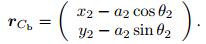
|
(5) |
For convenience of expression, the following notations are used in this paper:

|
(6) |

|
(7) |
where Am × n represents an m × n matrix, and t is time.
2.2 Normal contact force modelThe simulation needs to develop a mathematical model for the revolute clearance joint A in the slider-crank mechanism, as shown in Fig. 2. The eccentricity vector d connecting the centers of the bearing and the journal of joint A is defined as

|
| Fig. 2 The revolute joint A with clearance and small penetration |
|
|

|
(8) |
The unit eccentricity vector n which is normal to the surfaces of collision between the bearing and the journal can then be expressed as

|
(9) |
The unit vector has the same direction as the line of centers of the bearing and the journal. Rotating the vector n in the counter clockwise direction by π /2 gives the unit tangential vector τ,

|
(10) |
When the journal contacts with the bearing, appropriate normal and tangential contact force models are employed and the resultant forces are included as generalized forces in the dynamic equations of the mechanism. In the present study, the normal contact force is calculated by a Hertzian-based contact force model given by Hunt and Crossley[56] as

|
(11) |
where Fn represents the normal contact force. δ and 

|
(12) |
where Rj and Rb are the radii of the journal and the bearing, respectively. σ1 and σ2 denote the material parameters for the crank and rod AB, respectively, and they are given by

|
(13) |
in which Eι and νι are the material Young's modulus and Poisson's ratio associated with the corresponding body, respectively. The hysteresis factor χ can be obtained as[59]

|
(14) |
where εr is the restitution coefficient, and 
As shown in Fig. 2, the penetration depth between the journal and the bearing can be calculated by

|
(15) |
The Coulomb dry friction model is a fundamental and simple friction model for dry contacting surfaces. It has good capability to simulate stiction and to capture the stick-slip motion, and it requires a smaller number of selected parameters and less computational time than the bristle-based friction models[36-37]. Besides, the coefficients of Coulomb friction can be easily obtained by consulting handbooks on friction or by doing experiments. Therefore, the Coulomb dry friction model is employed as the tangential contact model for the components of joint A in this paper.
The Coulomb dry friction model is expressed as

|
(16) |
where Fτ is the frictional force acting on the contact points between the journal and the bearing[60]. vτ is the relative tangential velocity of the contact points, and aτ = dvτ /dt. μs and μ are the coefficients of static and kinetic friction, respectively. μs is generally larger than μ. sgn(x), which is the sign function, is defined by

|
(17) |
while Sgn(x), which is the multivalued function, is defined as[61]

|
(18) |
In order to make comparison, a modified Coulomb friction model which many researchers have adopted is given here,

|
(19) |
where cd is a dynamic coefficient of correction, which is expressed as

|
(20) |
in which v0 and v1 are given tolerances for the relative tangential velocity[12-19, 30-33]. These two Coulomb friction models are illustrated in Fig. 3.

|
| Fig. 3 Two Coulomb friction models |
|
|
For a kinematically constrained rigid multibody system, the Lagrange equations of the first kind are given by

|
(21) |
where T is the kinetic energy of the mechanism. 

The kinetic energy of the mechanism is expressed as

|
(22) |
where M is the positive definite mass matrix

|
(23) |
The vector of generalized forces is expressed as

|
(24) |
where

|
and

|
in which F is the vector of generalized externally applied forces,

|
(25) |
or

|
(26) |
and

|
The constraint equations can be expressed as

|
(27) |
or

|
(28) |
To keep the constraint violations under control, the method of Baumgarte stabilization[63] can be used,

|
(29) |
where αB>0, and βB>0, and they can be chosen following the instruction of Ref. [64].
From Eq. (29), the following equation can be obtained:

|
(30) |
where 

|
(31) |
Equation (31) is inserted into Eq. (30), which gives the vector of Lagrange multipliers,

|
(32) |
where

|
Substituting Eq. (32) into Eq. (31) leads to the differential dynamic equations for the system,

|
(33) |
where

|
In order to solve the dynamic equation (33), the frictional force between the journal and the bearing of the clearance joint A and Fτ must be determined. When vτ ≠ 0, the journal is sliding relative to the bearing. Therefore, the frictional force can be calculated by the first equation of Eq. (16). When vτ = 0, there are the following three cases:
(ⅰ) 
(ⅱ) 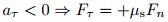
(ⅲ) 
Therefore, when vτ = 0, the determination of the stick-slip transition and the calculation of the static frictional force between the journal and bearing will be difficult. Using the non-smooth dynamic approach[48], one can transform this problem to an LCP and solve it.
An LCP is a set of linear equations that can be expressed as

|
(34) |
subject to inequality complementarity conditions

|
(35) |
for which the vectors u and v can be calculated for given A and b[65]. That is to say, the LCP is the problem of finding solutions u ∈ ℝn and v ∈ ℝn for conditions (35) and Eq. (34), in which b is a given n-dimensional vector, and A is a given n × n matrix.
When vτ = 0, the positive and negative parts of the acceleration aτ are defined as[66]

|
(36) |
The saturations of friction are defined as[66]

|
(37) |
Then, the accelerations aτ+ and aτ- are complementary to the friction saturations Fτ+ and Fτ-, respectively. From Eqs. (36) and (37), one can obtain the following three equations:

|
(38) |
The above equations will be used in the next subsection.
3.2 LCP algorithm for the static frictional forceTaking the derivative of Eq. (8) versus time yields

|
(39) |
where

|
Taking the derivative of Eq. (10) with respect to time leads to

|
(40) |
where
|
Substituting Eq. (39) into Eq. (40) results in

|
(41) |
The relative tangential velocity of the contact points between the journal and bearing is

|
(42) |
where

|
Therefore, aτ can be expressed as

|
(43) |
where

|
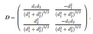
Inserting Eq. (33) into Eq. (43) yields

|
(44) |
Combining Eq. (44) with Eq. (38) results in

|
(45) |
where

|
(46) |
Some numerical methods for the LCP, such as Lemke's algorithm, can be adopted to solve Eq. (45) and conditions (46) to obtain the solution Fτ-. Substituting Fτ- into the second equation of Eq. (38), the static frictional force Fτ can be calculated.
3.3 Trial-and-error algorithm for the static frictional forceAs the mechanism has only one pair of contact points, the trial-and-error algorithm can be employed, and the results generated by the trial-and-error algorithm can be compared with those yielded by the LCP algorithm to test the validity of the LCP algorithm. When vτ = 0, suppose aτ = 0 firstly. Then, Eq. (44) leads to

|
(47) |
If |Fτ| ≤ μsFn, the static frictional force is then solved by Eq. (47), otherwise the frictional force is determined by

|
(48) |
By using the LCP algorithm or the trial-and-error algorithm, the static frictional force Fτ can be obtained. Inserting Fτ into Eq. (33), the dynamic equations can be solved by numerical methods for ordinary differential equations. In this study, Lemke's algorithm is used to solve the LCP, and the ODE15s in MATLAB is adopted to solve Eq. (33). The simulation flowchart is given in Fig. 4.

|
| Fig. 4 Simulation flowchart |
|
|
As the focus of this study is to investigate the influence of using the two Coulomb friction models on the dynamical response of the slider-crank mechanism with a revolute clearance joint, the journal and the bearing of the clearance joint are in permanent contact in all numerical examples, which is so called "contact or following mode"[15].
The parameters of the slider-crank mechanism are set as

|
The coefficients for the Hertzian-based contact force model are[46-47]

|
The viscous damping coefficients for the crank and the slider are

|
The Baumgarte stabilization constants are set as

|
The gravitational acceleration is set as g = 9.8 m/s2. When vτ ≤ ε = 1 × 10⁻⁵ m/s, the relative tangential velocity of the contact points between the journal and bearing is treated as zero[68-69].
The velocity tolerances for the modified Coulomb friction model are set as

|
In this example, the crank is driven by a given sinusoidal driving torque,

|
The initial conditions of the mechanism are set as

|
Using the above initial conditions, the dynamic response is simulated with the following four cases in the revolute clearance joint A: (ⅰ) no friction; (ⅱ) using the modified Coulomb friction model with μ = 0.10; (ⅲ) using the Coulomb dry friction model with μ = μs = 0.10; (ⅳ) using the Coulomb dry friction model with μ = 0.10 and μs = 0.11. The dynamic response of the slider-crank mechanism with ideal joints (ideal slider-crank mechanism) is also simulated to compare with the above results. Figure 5 shows the time histories of angular position and angular velocity of the crank. When the revolute clearance joint has no friction, the motion of the slider-crank mechanism with a revolute clearance joint is identical with ideal slider-crank mechanism, as shown in Fig. 5(a). Because of the friction in the clearance joint A, the amplitude of the crank angular position reduces and the motion lags, as illustrated in Figs. 5(b), 5(c), and 5(d). The modified Coulomb friction model does not capture stick-slip motion, but the Coulomb dry friction model does.

|
Fig. 5 Time histories of θ1 and  |
|
|
Figure 6 depicts the time histories of the relative tangential velocity, the frictional force, and the normal contact force of the contact points between the journal and the bearing. The contact points show stick-slip motion if the Coulomb dry friction model is applied, as shown in Figs. 6(b), 6(c), and 6(d), where Fig. 6(d) is a magnified view of the blue rectangle in Fig. 6(c). Due to the difference between static and kinetic friction coefficients, the relative tangential velocity and the contact forces oscillate severely when the contact points move from stick to slip, as shown in Figs. 6(c) and 6(d).

|
| Fig. 6 Time histories of 5 000vτ, 3Fτ, and Fn based on different friction models: (a) the modified Coulomb friction model with μ = 0.10; (b) the Coulomb dry friction model with μ = μs = 0.10; (c) the Coulomb dry friction model with μ = 0.10 and μs = 0.11; (d) the magnified view of the blue rectangle in Fig. 6(c) (color online) |
|
|
Figure 7 shows the comparison of the crank angular position based on two different algorithms: trial-and-error algorithm and LCP algorithm, using the Coulomb dry friction model with μ = 0.10 and μs = 0.11. It can be seen that the two different algorithms yield identical results.

|
| Fig. 7 Time histories of the crank angular position θ1 using different algorithms (color online) |
|
|
In order to investigate the differences between the modified Coulomb friction model and the Coulomb dry friction model, Fig. 8 gives the plots of the ratio Fτ /Fn versus vτ using the two Coulomb friction models. It can be observed from Fig. 8 that the Coulomb dry friction model exhibits the stick friction characteristics when the relative tangential velocity is in the vicinity of zero.

|
| Fig. 8 Plots of Fτ /Fn versus vτ for the two Coulomb friction models: (a) the Coulomb dry friction model; (b) the modified Coulomb friction model |
|
|
In this example, the crank rotates with a given rheonomic constraint,

|
The initial conditions of the mechanism are set as

|
The dynamic response of the mechanism is simulated for the revolute clearance joint A modeled by the following four cases: (ⅰ) no friction; (ⅱ) the modified Coulomb friction model with μ = 0.050; (ⅲ) the Coulomb dry friction model with μ = μs = 0.050; (ⅳ) the Coulomb dry friction model with μ = 0.050 and μs = 0.055. The dynamic response of ideal slider-crank mechanism is also simulated to compare with the above results. In this system, the Lagrange multiplier λ1 corresponding to the rheonomic constraint is the driving torque acting on the crank. The time histories of λ1 for the clearance joint A modeled by Cases (ⅰ), (ⅱ), (ⅲ), and for the ideal slider-crank mechanism are given in Figs. 9(a) and 9(b), where Fig. 9(b) is a magnified view of the blue rectangle in Fig. 9(a). Due to the transient effect of stick friction, the driving torque acting on the crank are slightly different using the two different Coulomb friction models. The time histories of λ1 for the clearance joint A modeled by Cases (ⅲ) and (ⅳ) and for the ideal slider-crank mechanism are shown in Figs. 9(c) and 9(d), where Fig. 9(d) is a magnified view of the blue rectangle in Fig. 9(c). Figure 10 illustrates the time histories of relative tangential velocity, frictional force, and normal contact force of the contact points between the journal and the bearing in Case (ⅳ). Because of the difference between the static and kinetic friction coefficients, the relative tangential velocity, the contact forces, and the driving torque acting on the crank oscillate severely when the contact points move from stick to slip, as shown in Figs. 9(c), 9(d), and 10.

|
| Fig. 9 Time histories of the Lagrange multiplier λ1 using different friction models: (a) the modified Coulomb friction model with μ = 0.050 and the Coulomb dry friction model with μ = μs = 0.050; (b) the magnified view of the blue rectangle in Fig. 9(a); (c) the Coulomb dry friction model with μ = μs = 0.050 versus μ = 0.050 and μs = 0.055; (d) the magnified view of the blue rectangle in Fig. 9(c) (color online) |
|
|

|
| Fig. 10 Time histories of 5 000vτ, and 3Fτ, and Fn: (a) using the Coulomb dry friction model with μ=0.050 and μs = 0.055 and (b) the magnified view of the blue rectangle in Fig. 10(a) (color online) |
|
|
Figure 11 shows the time histories of the Lagrange multiplier λ1 using the Coulomb dry friction model with different friction coefficients. Simulation results show that lager friction coefficients correspond to larger amplitudes of the Lagrange multiplier λ1. In other words, the increase in the friction coefficient leads to the increase in the amplitude of the driving torque on the crank, which is consistent with our common sense.

|
| Fig. 11 Time histories of the Lagrange multiplier λ1 using the Coulomb dry friction model with different friction coefficients (color online) |
|
|
In this example, the driving crank torque is zero. The initial conditions of the mechanism are set as

|
Using the above initial conditions, the dynamic behavior of the mechanism is simulated with the following three cases in the revolute clearance joint A: (ⅰ) no friction; (ⅱ) using the modified Coulomb friction model with μ = 0.15; (ⅲ) using the Coulomb dry friction model with μ = 0.15 and μs = 0.20. The dynamic response of ideal slider-crank mechanism is also simulated to compare with the above results. Figure 12 illustrates the time histories of the crank angular position θ1 in these cases. If the Coulomb dry friction model is adopted as the tangential contact force model for the revolute clearance joint A, the system can balance at θ1 = π - 0.01 due to static friction. However, the crank can hardly keep balance in other cases, and it moves from θ1 = π - 0.01 to θ1 =0, as shown in Fig. 12.

|
| Fig. 12 Time histories of the crank angular position θ1 using different models (color online) |
|
|
Figure 13 gives the time histories of relative tangential velocity and frictional force of the contact points between the journal and the bearing in Case (ⅲ). In this case, the relative tangential velocity of the contact points is zero. Then, the contact points are subject to static frictional forces, which are unequal to zero.

|
| Fig. 13 Time histories of 1 000vτ and Fτ using the Coulomb dry friction model (color online) |
|
|
This paper aims at comparing and analyzing the effects of the Coulomb dry friction model and the modified Coulomb friction model on the dynamic behavior of slider-crank mechanism with a revolute clearance joint. The normal force of the contact points between the journal and the bearing is expressed as a nonlinear function of the penetration depth and penetration velocity. The tangential force is described by the Coulomb dry friction model, which has stick friction characteristics. The dynamic equations of the system are obtained by using the Lagrange equations of the first kind and the Baumgarte stabilization method. The static frictional force is solved via the trial-and-error algorithm and the LCP algorithm to compare the simulation results. The results generated by using the Coulomb dry friction model are compared with those yielded by the modified Coulomb friction model.
The study shows that due to stick friction, the slider-crank mechanism with a revolute clearance joint may exhibit stick-slip motion, and can balance at some special positions, while the mechanism with ideal joints cannot. Because of the difference between the static and kinetic friction coefficients for the Coulomb dry friction model, the relative tangential velocity of the contact points, the contact forces, and the driving crank torque may oscillate severely when the contact points move from stick to slip.
| [1] | GUMMER, A. and SAUER, B. Modeling planar slider-crank mechanisms with clearance joints in RecurDyn. Multibody System Dynamics, 31(2), 127-145 (2014) doi:10.1007/s11044-012-9339-2 |
| [2] | ABDALLAH, M. A. B., KHEMILI, I., and AIFAOUI, N. Numerical investigation of a flexible slider-crank mechanism with multijoints with clearance. Multibody System Dynamics, 38(2), 173-199 (2016) doi:10.1007/s11044-016-9526-7 |
| [3] | CHEN, Y., SUN, Y., PENG, B., and CAO, C. A comparative study of joint clearance effects on dynamic behavior of planar multibody mechanical systems. Latin American Journal of Solids and Structures, 13(15), 2815-2833 (2016) doi:10.1590/1679-78253021 |
| [4] | LI, Y., CHEN, G., SUN, D., GAO, Y., and WANG, K. Dynamic analysis and optimization design of a planar slider-crank mechanism with flexible components and two clearance joints. Mechanism and Machine Theory, 99, 37-57 (2016) doi:10.1016/j.mechmachtheory.2015.11.018 |
| [5] | YANG, Y., CHENG, J. R., and ZHANG, T. Vector form intrinsic finite element method for planar multibody systems with multiple clearance joints. Nonlinear Dynamics, 86(1), 421-440 (2016) doi:10.1007/s11071-016-2898-7 |
| [6] | SONG, Z., YANG, X., LI, B., XU, W., and HU, H. Modular dynamic modeling and analysis of planar closed-loop mechanisms with clearance joints and flexible links. Proceedings of the Institution of Mechanical Engineers, Part C: Journal of Mechanical Engineering Science, 231(3), 522-540(2017) |
| [7] | EBRAHIMI, S., SALAHSHOOR, E., and MORADI, S. Vibration performance evaluation of planar flexible multibody systems with joint clearance. Journal of the Brazilian Society of Mechanical Sciences and Engineering, 39, 4895-4909 (2017) doi:10.1007/s40430-017-0855-0 |
| [8] | ERKAYA, S. and UZMAY, Í. Modeling and simulation of joint clearance effects on mechanisms having rigid and flexible links. Journal of Mechanical Science and Technology, 28(8), 2979-2986 (2014) doi:10.1007/s12206-014-0705-2 |
| [9] | ERKAYA, S. and DOǦAN, S. A comparative analysis of joint clearance effects on a rticulated and partly compliant mechanisms. Nonlinear Dynamics, 81(1/2), 323-341 (2015) |
| [10] | ERKAYA, S., DOǦAN, S., and ULUS, Ş. Effects of joint clearance on the dynamics of a partly compliant mechanism:numerical and experimental studies. Mechanism and Machine Theory, 88, 125-140 (2015) doi:10.1016/j.mechmachtheory.2015.02.007 |
| [11] | ERKAYA, S., DOǦAN, S., and ŞEFKATLIOǦLU, E. Analysis of the joint clearance effects on a compliant spatial mechanism. Mechanism and Machine Theory, 104, 255-273 (2016) doi:10.1016/j.mechmachtheory.2016.06.009 |
| [12] | FLORES, P., AMBRÓSIO, J., CLARO, J., and LANKARANI, H. Translational joints with clearance in rigid multibody systems. Journal of Computational and Nonlinear Dynamics, 3(1), 011007 (2008) doi:10.1115/1.2802113 |
| [13] | MACHADO, M., COSTA, J., SEABRA, E., and FLORES, P. The effect of the lubricated revolute joint parameters and hydrodynamic force models on the dynamic response of planar multibody systems. Nonlinear Dynamics, 69(1), 635-654 (2012) |
| [14] | FLORES, P., KOSHY, C., LANKARANI, H., AMBRÓSIO, J., and CLARO, J. C. P. Numerical and experimental investigation on multibody systems with revolute clearance joints. Nonlinear Dynamics, 65(4), 383-398 (2011) doi:10.1007/s11071-010-9899-8 |
| [15] | FLORES, P. A parametric study on the dynamic response of planar multibody systems with multiple clearance joints. Nonlinear Dynamics, 61(4), 633-653 (2010) doi:10.1007/s11071-010-9676-8 |
| [16] | ZHANG, Z., XU, L., FLORES, P., and LANKARANI, H. M. A Kriging model for dynamics of mechanical systems with revolute joint clearances. Journal of Computational and Nonlinear Dynamics, 9(3), 031013 (2014) doi:10.1115/1.4026233 |
| [17] | MARQUES, F., ISAAC, F., DOURADO, N., and FLORES, P. An enhanced formulation to model spatial revolute joints with radial and axial clearances. Mechanism and Machine Theory, 116, 123-144 (2017) doi:10.1016/j.mechmachtheory.2017.05.020 |
| [18] | MARQUES, F., ISAAC, F., DOURADO, N., SOUTO, A. P., FLORES, P., and LANKARANI, H. M. A study on the dynamics of spatial mechanisms with frictional spherical clearance joints. Journal of Computational and Nonlinear Dynamics, 12(5), 051013 (2017) doi:10.1115/1.4036480 |
| [19] | ISAAC, F., MARQUES, F., DOURADO, N., and FLORES, P. Recent developments on cylindrical contact force models with realistic properties. New Trends in Mechanism and Machine Science, Springer, Berlin, 211-219(2017) |
| [20] | RAHMANIAN, S. and GHAZAVI, M. R. Bifurcation in planar slider-crank mechanism with revolute clearance joint. Mechanism and Machine Theory, 91, 86-101 (2015) doi:10.1016/j.mechmachtheory.2015.04.008 |
| [21] | FARAHAN, S. B., GHAZAVI, M. R., and RAHMANIAN, S. Bifurcation in a planar four-bar mechanism with revolute clearance joint. Nonlinear Dynamics, 87(2), 955-973 (2017) doi:10.1007/s11071-016-3091-8 |
| [22] | FARAHAN, S. B., GHAZAVI, M. R., and RAHMANIAN, S. Nonlinear dynamic analysis of a fourbar mechanism having revolute joint with clearance. Journal of Theoretical and Applied Vibration and Acoustics, 2(1), 91-106 (2016) |
| [23] | BAI, Z., CHEN, J., and SUN, Y. Effects of contact force model on dynamics characteristics of mechanical system with revolute clearance joints. Iranian Journal of Science and Technology. Transactions of Mechanical Engineering, 38(M2), 375-388 (2014) |
| [24] | BAI, Z. F., SHI, X., and WANG, P. P. Effects of body flexibility on dynamics of mechanism with clearance joint. Mechanism and Machine Science: Proceedings of ASIAN MMS 2016 & CCMMS 2016, Springer, Berlin, 1239-1247(2017) |
| [25] | BAI, Z. F. and SUN, Y. A study on dynamics of planar multibody mechanical systems with multiple revolute clearance joints. European Journal of Mechanics-A/Solids, 60, 95-111 (2016) doi:10.1016/j.euromechsol.2016.06.009 |
| [26] | BAI, Z. F., ZHAO, Y., and WANG, X. G. Wear analysis of revolute joints with clearance in multibody systems. Science China Physics. Mechanics and Astronomy, 56(8), 1581-1590 (2013) doi:10.1007/s11433-013-5125-2 |
| [27] | BAI, Z. F., ZHANG, H. B., and SUN, Y. Wear prediction for dry revolute joint with clearance in multibody system by integrating dynamics model and wear model. Latin American Journal of Solids and Structures, 11(14), 2624-2647 (2014) doi:10.1590/S1679-78252014001400005 |
| [28] | QI, Z., XU, Y., LUO, X., and YAO, S. Recursive formulations for multibody systems with frictional joints based on the interaction between bodies. Multibody System Dynamics, 24(2), 133-166 (2010) doi:10.1007/s11044-010-9213-z |
| [29] | WANG, G., QI, Z., and WANG, J. A differential approach for modeling revolute clearance joints in planar rigid multibody systems. Multibody System Dynamics, 39(4), 311-335 (2017) doi:10.1007/s11044-016-9552-5 |
| [30] | TIAN, Q., ZHANG, Y., CHEN, L., and YANG, J. Simulation of planar flexible multibody systems with clearance and lubricated revolute joints. Nonlinear Dynamics, 60(4), 489-511 (2010) doi:10.1007/s11071-009-9610-0 |
| [31] | TIAN, Q., LIU, C., MACHADO, M., and FLORES, P. A new model for dry and lubricated cylindrical joints with clearance in spatial flexible multibody systems. Nonlinear Dynamics, 64(1), 25-47 (2011) |
| [32] | TIAN, Q., SUN, Y., LIU, C., HU, H., and FLORES, P. Elastohydrodynamic lubricated cylindrical joints for rigid-flexible multibody dynamics. Computers and Structures, 114, 106-120 (2013) |
| [33] | WANG, Z., TIAN, Q., HU, H., and FLORES, P. Nonlinear dynamics and chaotic control of a flexible multibody system with uncertain joint clearance. Nonlinear Dynamics, 86(3), 1571-1597 (2016) doi:10.1007/s11071-016-2978-8 |
| [34] | YAN, S. and GUO, P. Kinematic accuracy analysis of flexible mechanisms with uncertain link lengths and joint clearances. Proceedings of the Institution of Mechanical Engineers. Part C:Journal of Mechanical Engineering Science, 225(8), 1973-1983 (2011) doi:10.1177/0954406211401499 |
| [35] | XIANG, W., YAN, S., and WU, J. A comprehensive method for joint wear prediction in planar mechanical systems with clearances considering complex contact conditions. Science China Technological Sciences, 58(1), 86-96 (2015) doi:10.1007/s11431-014-5685-z |
| [36] | MARQUES, F., FLORES, P., CLARO, J. P., and LANKARANI, H. M. A survey and comparison of several friction force models for dynamic analysis of multibody mechanical systems. Nonlinear Dynamics, 86(3), 1407-1443 (2016) doi:10.1007/s11071-016-2999-3 |
| [37] | PENNESTR, Ì E., ROSSI, V., SALVINI, P., and VALENTINI, P. P. Review and comparison of dry friction force models. Nonlinear Dynamics, 83(4), 1785-1801 (2016) doi:10.1007/s11071-015-2485-3 |
| [38] | MUVENGEI, O., KIHIU, J., and IKUA, B. Dynamic analysis of planar multi-body systems with LuGre friction at differently located revolute clearance joints. Multibody System Dynamics, 28(4), 369-393 (2012) doi:10.1007/s11044-012-9309-8 |
| [39] | MUVENGEI, O., KIHIU, J., and IKUA, B. Dynamic analysis of planar rigid-body mechanical systems with two-clearance revolute joints. Nonlinear Dynamics, 73(1/2), 259-273 (2013) |
| [40] | ZHAO, B., ZHANG, Z. N., FANG, C. C., DAI, X. D., and XIE, Y. B. Modeling and analysis of planar multibody system with mixed lubricated revolute joint. Tribology International, 98, 229-241 (2016) doi:10.1016/j.triboint.2016.02.024 |
| [41] | ZHENG, E. and ZHOU, X. Modeling and simulation of flexible slider-crank mechanism with clearance for a closed high speed press system. Mechanism and Machine Theory, 74(6), 10-30 (2014) |
| [42] | ZHENG, E., ZHU, R., ZHU, S., and LU, X. A study on dynamics of flexible multi-link mechanism including joints with clearance and lubrication for ultra-precision presses. Nonlinear Dynamics, 83(1/2), 137-159 (2016) |
| [43] | LIU, C., ZHAO, Z., and CHEN, B. The bouncing motion appearing in a robotic system with unilateral constraint. Nonlinear Dynamics, 49(1), 217-232 (2006) |
| [44] | ZHAO, Z., LIU, C., and CHEN, B. The Painlevé paradox studied at a 3D slender rod. Multibody System Dynamics, 19(4), 323-343 (2008) doi:10.1007/s11044-007-9098-7 |
| [45] | ZHAO, Z., CHEN, B., LIU, C., and HAI, J. Impact model resolution on Painlevé's paradox. Acta Mechanica Sinica, 20(6), 649-660 (2004) doi:10.1007/BF02485869 |
| [46] | WANG, X. and LV, J. Modeling and simulation of dynamics of a planar-motion rigid body with friction and surface contact. International Journal of Modern Physics B, 31, 1744021 (2017) doi:10.1142/S0217979217440210 |
| [47] | XU, Z., WANG, Q., and WANG, Q. Y. Numerical method for dynamics of multi-body systems with two-dimensional Coulomb dry friction and nonholonomic constraints. Applied Mathematics and Mechanics (English Edition), 38(12), 1733-1752 (2017) doi:10.1007/s10483-017-2285-8 |
| [48] | PFEIFFER, F. On non-smooth dynamics. Meccanica, 43(5), 533-554 (2008) doi:10.1007/s11012-008-9139-1 |
| [49] | FLORES, P., LEINE, R., and GLOCKER, C. Modeling and analysis of planar rigid multibody systems with translational clearance joints based on the non-smooth dynamics approach. Multibody System Dynamics, 23(2), 165-190 (2010) doi:10.1007/s11044-009-9178-y |
| [50] | ZHUANG, F. and WANG, Q. Modeling and simulation of the nonsmooth planar rigid multibody systems with frictional translational joints. Multibody System Dynamics, 29(4), 403-423 (2013) |
| [51] | ZHUANG, F. and WANG, Q. Modeling and analysis of rigid multibody systems with driving constraints and frictional translation joints. Acta Mechanica Sinica, 30(3), 437-446 (2014) doi:10.1007/s10409-014-0021-1 |
| [52] | WANG, Q., PENG, H., and ZHUANG, F. A constraint-stabilized method for multibody dynamics with friction-affected translational joints based on HLCP. Discrete and Continuous Dynamical Systems Series B, 16(2), 589-605 (2011) doi:10.3934/dcdsb |
| [53] | KRINNER, A. and THÜMMEL, T. Non-smooth behaviour of a linkage mechanism with revolute clearance joints. New Advances in Mechanisms, Transmissions and Applications, Springer, Berlin, 233-241(2014) |
| [54] | AKHADKAR, N., ACARY, V., and BROGLIATO, B. Multibody systems with 3D revolute joints with clearances:an industrial case study with an experimental validation. Multibody System Dynamics, 42(3), 249-282 (2018) doi:10.1007/s11044-017-9584-5 |
| [55] | AKHADKAR, N., ACARY, V., and BROGLIATO, B. 3D revolute joint with clearance in multibody systems. Computational Kinematics (2018) |
| [56] | HUNT, K. H. and CROSSLEY, F. R. E. Coefficient of restitution interpreted as damping in vibroimpact. Journal of Applied Mechanics, 42(2), 440-445 (1975) doi:10.1115/1.3423596 |
| [57] | JOHNSON, K. L. One hundred years of Hertz contact. Proceedings of the Institution of Mechanical Engineers, 196, 363-378 (1982) doi:10.1243/PIME_PROC_1982_196_039_02 |
| [58] | KOSHY, C. S., FLORES, P., and LANKARANI, H. M. Study of the effect of contact force model on the dynamic response of mechanical systems with dry clearance joints:computational and experimental approaches. Nonlinear Dynamics, 73(1/2), 325-338 (2013) |
| [59] | LANKARANI, H. M. and NIKRAVESH, P. E. A contact force model with hysteresis damping for impact analysis of multibody systems. Journal of Mechanical Design, 112(3), 369-376 (1990) doi:10.1115/1.2912617 |
| [60] | KUNZE, M. Non-Smooth Dynamical Systems, Springer, Berlin, 1-6 (2000) |
| [61] | GLOCKER, C. Set-valued force laws: dynamics of non-smooth systems. Lecture Notes in Applied and Computational Mechanics, 1, Springer-Verlag, Berlin/Heidelberg (2001) |
| [62] | NIKRAVESH, P. E. Computer-Aided Analysis of Mechanical Systems, Prentice-Hall, Inc., New Jersey (1988) |
| [63] | BAUMGARTE, J. Stabilization of constraints and integrals of motion in dynamical systems. Computer Methods in Applied Mechanics and Engineering, 1(1), 1-16 (1972) doi:10.1016/0045-7825(72)90018-7 |
| [64] | FLORES, P., MACHADO, M., SEABRA, E., and SILVA, M. T. A parametric study on the Baumgarte stabilization method for forward dynamics of constrained multibody systems. Journal of Computational and Nonlinear Dynamics, 6(1), 011019 (0110) |
| [65] | COTTLE, R. W. and DANTZIG, G. B. Complementary pivot theory of mathematical programming. Linear Algebra and Its Applications, 1(1), 103-125 (1968) doi:10.1016/0024-3795(68)90052-9 |
| [66] | LEINE, R. I., CAMPEN, D. H. V., and GLOCKER, C. H. Nonlinear dynamics and modeling of various wooden toys with impact and friction. Journal of Vibration and Control, 9(1/2), 25-78 (2003) |
| [67] | QI, F., WANG, T., and LI, J. The elastic contact influences on passive walking gaits. Robotica, 29(5), 787-796 (2011) doi:10.1017/S0263574710000779 |
| [68] | LIU, L., LIU, H., WU, Z., and YUAN, D. A new method for the determination of the zero velocity region of the Karnopp model based on the statistics theory. Mechanical Systems and Signal Processing, 23(5), 1696-1703 (2009) doi:10.1016/j.ymssp.2009.01.002 |
| [69] | BICAKCI, S., AKDAS, D., and KARAOGLAN, A. D. Optimizing Karnopp friction model parameters of a pendulum using RSM. European Journal of Control, 20(4), 180-187 (2014) doi:10.1016/j.ejcon.2014.04.001 |